EasyManuals Logo
Home>UNI-T>Multimeter>UT203

UNI-T UT203 User Manual

UNI-T UT203
47 pages
To Next Page IconTo Next Page
To Previous Page IconTo Previous Page
Page #23 background imageLoading...
Page #23 background image
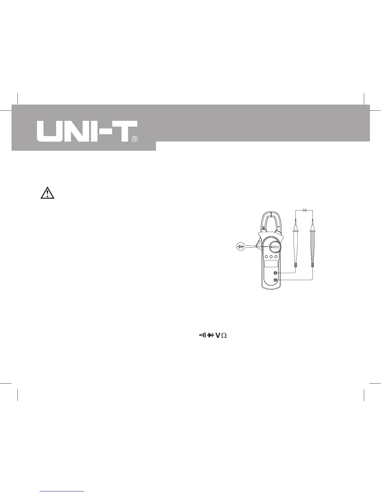
C. Testing Diodes (see figure 5)
Warning
To avoid damages to the Meter or to the devices
under test, disconnect circuit power and discharge
all the high-voltage capacitors before testing
diodes.
Use the diode test to check diodes, transistors, and
other semiconductor devices. The diode test sends
a current through the semicondutor junction, then
measure the voltage drop across the junction. A
good silicon junction drops between 0.5V and 0.8V.
To test the diode out of a circuit, connect the Meter
as follows:
Insert the red test lead into the Hz Duty% terminal and the black test lead
into the COM terminal.
1.
(figure 5)
Red Black
Model UT203/204: OPERATING MANUAL
22

Questions and Answers:

Question and Answer IconNeed help?

Do you have a question about the UNI-T UT203 and is the answer not in the manual?

UNI-T UT203 Specifications

General IconGeneral
Frequency range0.01 - 1000 kHz
AC current range40 - 400 A
AC voltage range4 - 600 V
Continuity checkYes
DC voltage range0.4 - 600 V
Basic accuracy (frequency)±(0.1%+3)
Basic accuracy (DC current)±(2%+3)
Basic accuracy (DC voltage)±(0.8%+1)
Basic accuracy (resistance)±(1%+2)
Dimensions (WxDxH)76 x 30 x 210 mm
Battery voltage9 V
Weight and Dimensions IconWeight and Dimensions
Weight200 g

Related product manuals