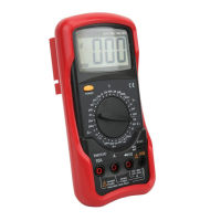
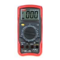
19
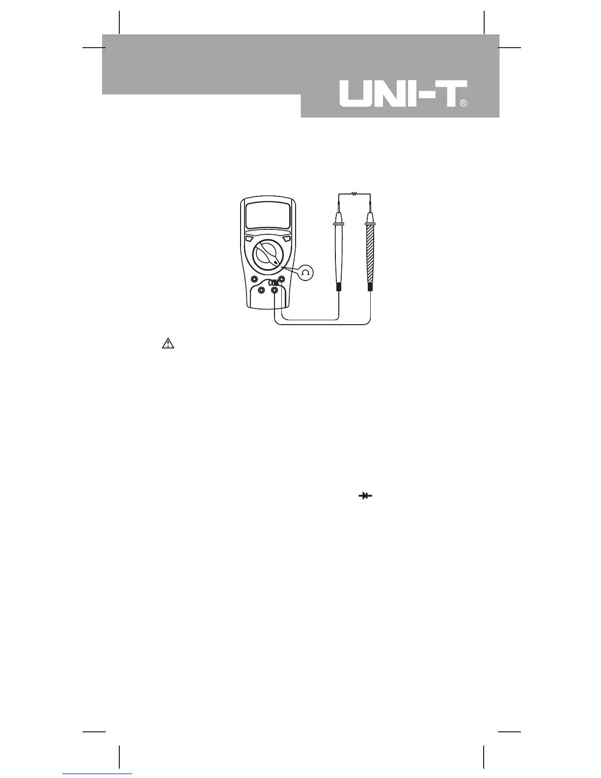
E. Measuring Resistance (see figure 7)
Warning
To avoid damages to the Meter or to the devices under
test, disconnect circuit power and discharge all the
high-voltage capacitors before measuring resistance.
The resistance ranges are:
The Model UT50A/UT50B: 200Ω, 2kΩ, 20kΩ, 200kΩ,
2MΩ, 20MΩand 200MΩ.
The Model UT50C: 200Ω, 2kΩ, 20kΩ, 200kΩ, 2MΩ
and 200MΩ.
To measure resistance, connect the Meter as follows:
1. Insert the red test lead into the VΩ terminal and
the black test lead into the COM terminal.
2. Set the rotary switch to an appropriate measurement
position inΩ range.
3. Connect the test leads across with the object being
measured.The measured value shows on the display.
Note
l The test leads can add 0.1Ωto 0.3Ω of error to the
resistance measurement.To obtain precision readings
in low-resistance, that is the range of 200Ω, short-
circuit the input terminals beforehand and record the
reading obtained (called this reading as X). (X) is
the additional resistance from the test lead.
Then use the equation:
Measurement Operation(7)
( figure 7)
red black
Model UT50A/B/C: OPERATING MANUAL
 Loading...