Measurement Operation (3)
Note
l In each range, the Meter has an input impedance
of 10M . This loading effect can cause measurement
errors in high impedance circuits. If the circuit
impedance is less than or equal to 10k , the error
is negligible (0.1% or less).
l When DC voltage measurement has been
completed, disconnect the connection between the
testing leads and the circuit under test.
B. Measuring Continuity, Diodes & Resistance
Warning
To avoid damages to the Meter or to the devices
under test, disconnect circuit power and discharge
all the high-voltage capacitors before measuring
continuity, diodes & resistance.
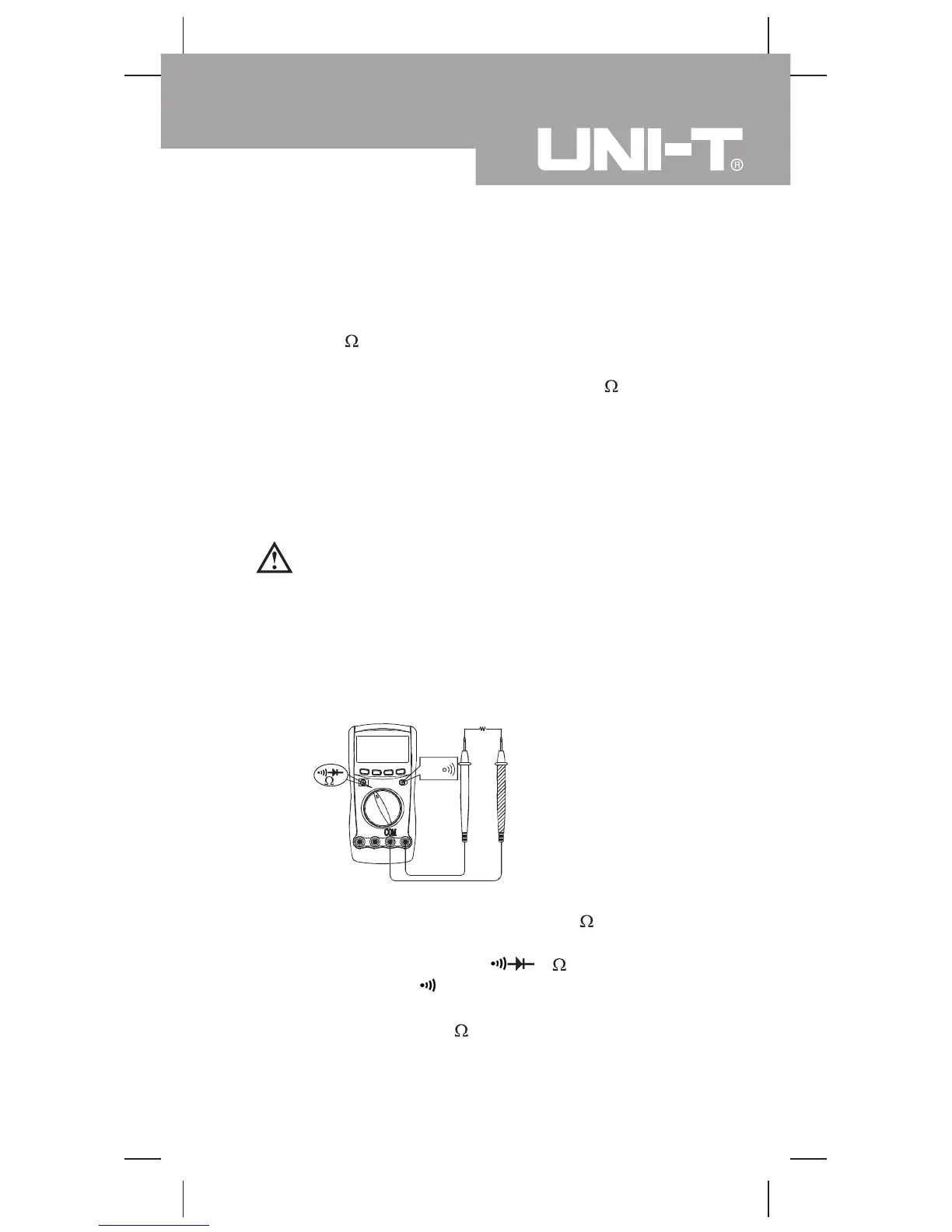
Testing for Continuity (see figure 5)
Select
(figure 5)
To test for continuity, connect the Meter as below:
1. Insert the red test lead into the HzV terminal and
the black test lead into the COM terminal.
2. Set the rotary switch to
and press BLUE
button to select
measurement mode.
3. The buzzer sounds if the resistance of a circuit under
test is less than 100 .
black
red
21
Model UT60A: OPERATING MANUAL

 Loading...