Measurement Operation (4)
Note
l The LCD displays
indicating the circuit being
tested is open.
l When continuity testing has been completed,
disconnect the connection between the testing leads
and the circuit under test.
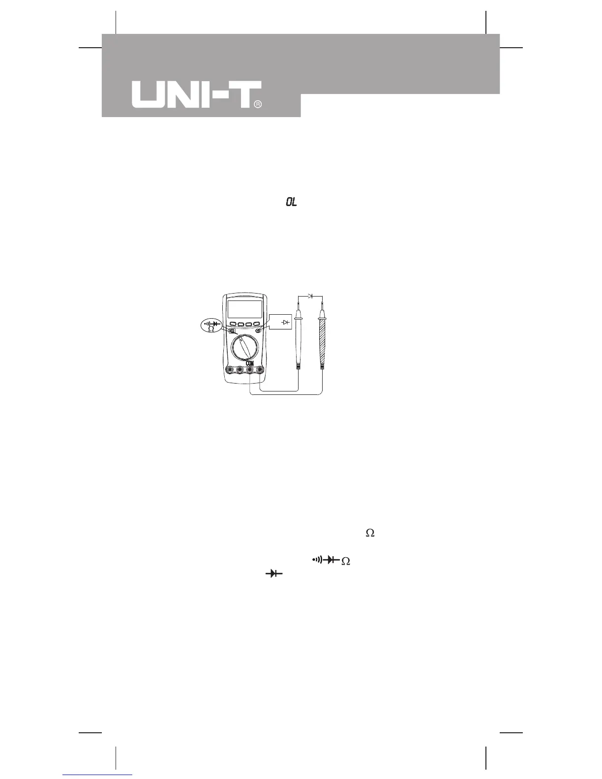
Testing Diodes (see figure 6)
Select
(figure 6)
Use the diode test to check diodes, transistors, and other
semiconductor devices. The diode test sends a current
through the semiconductor junction, and then measures
the voltage drop across the junction. A good silicon
junction drops between 0.5V and 0.8V.
To test a diode out of a circuit, connect the Meter as
follows:
1. Insert the red test lead into the HzV terminal and
the black test lead into the COM terminal.
2. Set the rotary switch to
and press BLUE
button to select
measurement mode.
3. For forward voltage drop readings on any
semiconductor component, place the red test lead
on the component's anode and place the black test
lead on the component's cathode.
The measured value shows on the display.
black
red
Model UT60A: OPERATING MANUAL
22

 Loading...