Measurement Operation (5)
Note
l In a circuit, a good diode should still produce a
forward voltage drop reading of 0.5V to 0.8V;
however, the reverse voltage drop reading can vary
depending on the resistance of other pathways
between the probe tips.
l Connect the test leads to the proper terminals as
said above to avoid error display.
l The LCD will display
indicating open-circuit for
wrong connection.
l The unit of diode is Volt (V), displaying the positive-
connection voltage-drop value.
l When diode testing has been completed, disconnect
the connection between the testing leads and the
circuit under test.
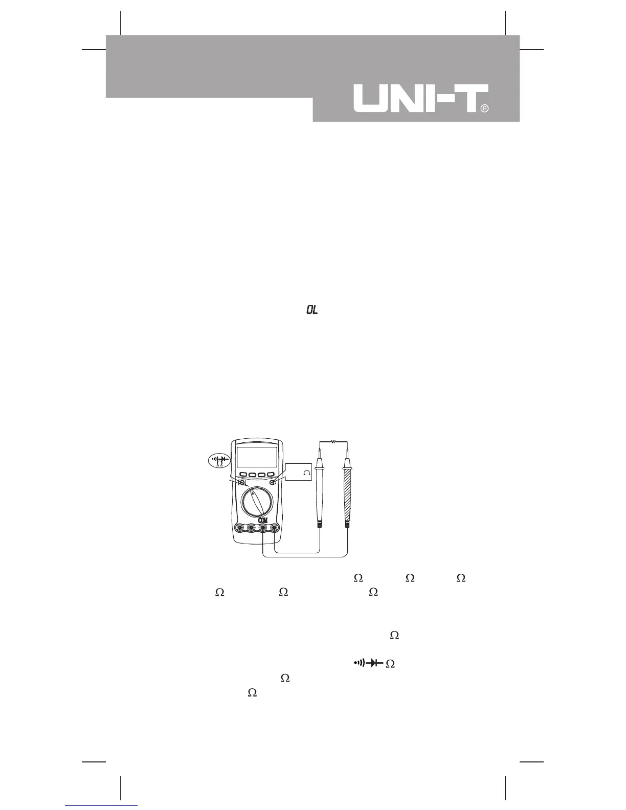
Resistance Measurement (see figure 7)
(figure 7)
Select
The resistance ranges are: 400.0 , 4.000k , 40.00k ,
400.0k , 4.000M and 40.00M . To measure
resistance, connect the Meter as follows:
1. Insert the red test lead into the HzV terminal and
the black test lead into the COM terminal.
2. Set the rotary switch to
, resistance
measurement ( ) is defaults or press BLUE button
to select measurement mode.
blackred
Model UT60A: OPERATING MANUAL
23