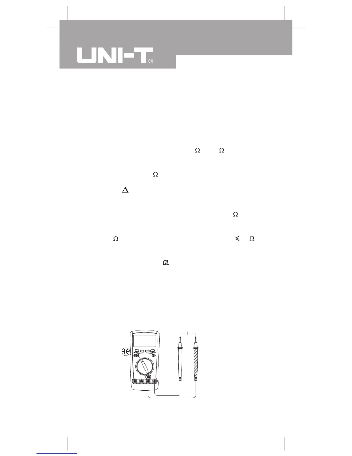
(figure 8)
Measurement Operation (6)
3. Connect the test leads across with the object being
measured.
The measured value shows on the display.
Note
l The test leads can add 0.1 to 0.2 of error to
resistance measurement. To obtain precision
readings in low-resistance measurement, that is the
range of 400.0 , short-circuit the input terminals
beforehand, using the relative value function button
REL
to automatically subtract the value measured
when the testing leads are short-circuited from the
reading.
l For high-resistance measurement (>1M ), it is
normal taking several seconds to obtain a stable
reading.
l If reading with shorted test leads is not
0.5 ,
check for loose test leads, incorrect function selection,
or enabled Data Hold function.
l The LCD displays
indicating open-circuit for the
tested resistor or the resistor value is higher than
the maximum range of the Meter.
l When resistance measurement has been completed,
disconnect the connection between the testing leads
and the circuit under test.
C. Capacitance Measurement (see figure 8)
blackred
Model UT60A: OPERATING MANUAL
24

 Loading...