42
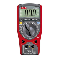
Model UT804: OPERATING MANUAL
mV
Hz
%
mV
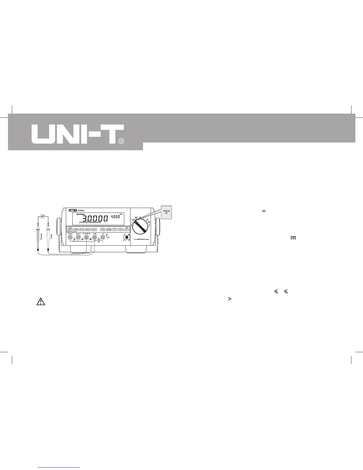
Figure 3-14. Frequency / Duty Cycle Measurement
I. Measuring Frequency / Duty Cycle To measure frequency and duty cycle, connect the
Meter as Figure 3-14 and do the following:
1. Insert the red test lead into the Hz terminal and the
black test lead into the COM terminal.
2. Set the rotary switch to and press SELECT
button to select the Hz measurement mode for
frequency measurement or % for duty cycle
measurement.
The SELECT button cycles among , frequency
and duty cycle.
3. Connect the test leads across with the object being
measured.
The measured value shows on the primary display.
Note
l
l
The requirement of Input amplitude “a” is as follows:
When 10Hz~40MHz: 200 mV a 30Vrms;
40MHz: Un-specified
When Hz or Duty Cycle measurement has been
completed, disconnect the connection between the
testing leads and the circuit under test and remove
the test leads away from the input terminals.
Warning
To avoid harms to you, please do not attempt to
input tested frequency voltage higher than 30V rms.
 Loading...