TCI-C-Universal Controller
Doc: 70-00-0123, Date: 20091020 © Vector Controls GmbH Page 12
Input Configuration
General
Alarms: Each input features low and high limit alarms. Each alarm is defined with a limit, a hysteresis and an enable
parameter. The limit specifies the input signal level required to trigger the alarm. The hysteresis defines the difference
between input signal and limit required to return the alarm state to normal. The hysteresis parameter is shared between
low and high limit alarms of the same input. Once an alarm is triggered it will be displayed as ALA1, ALA2, ALA3 and ALA4.
While the alarm is active the ALA display is steady.
The user is able to select if the alarm is to be acknowledged or not. If UP15 is set to ON: Once the alarm recovers the ALA
display will be blinking until acknowledged. Each alarm needs to be acknowledged by pressing the RIGHT key. IF UP15 is
OFF, the alarms will not be visible once the alarm condition is removed.
UI1 UI2 UI3 PT1000 In
Low limit alarm ALA1 ALA3 ALA5 ALA7
High limit alarm ALA2 ALA4 ALA6 ALA8
Averaging function: Averaging function is used to prevent unwanted fluctuation of sensor signals. The controller
measures every second the signal inputs. The input signal is now built over a number of measured values. Select how
many values should be used to calculate the averaging signal. Control speed will slow down when a large number of
samples are used for an averaging signal. This should be taken into account when defining the control parameters.
Compensation: Adjust input values if required
Universal Input
The universal input may be configured with a jumper to NTC temperature input or open contact, 0-10VDC or
4-20 mA. The jumper is located on the backside of the controller. The drawing on the right indicates the
jumper placement for each signal type. The factory setting is 0-10 VDC. Only place the jumper vertically.
The range of the input signal can be specified in software by setting a minimum and a maximum limit. The
limits are in percent of the full range.
The display value of the input signal may be specified according to its measuring range. For example a
pressure sensor has a 4-20 mA output and a pressure range of 0 – 200 Pa. It is possible to transform the
input signal into a different dimension by setting the lower and upper measuring range limit according to the
features of the sensor device. In our example the display will read 100 for a 12 mA signal. Range values
below 100 will have a resolution of 0.5, below 50 of 0.2 and below 25 of 0.1.
The smaller the measuring range is, the higher is the resolution. A signal of 0…100 may be displayed to a
resolution of 0.1 for the input measurement and 0.5 for the setpoint. 0…200 can only be shown with a resolution of 0.2
and 1.0 for the setpoint.
With the range parameter, larger numbers may be displayed. -50..205 may be multiplied x 10 or x 100. Largest
displayable values are -990…9999. Units may be °C/°F, % or Pa (displayed as P)
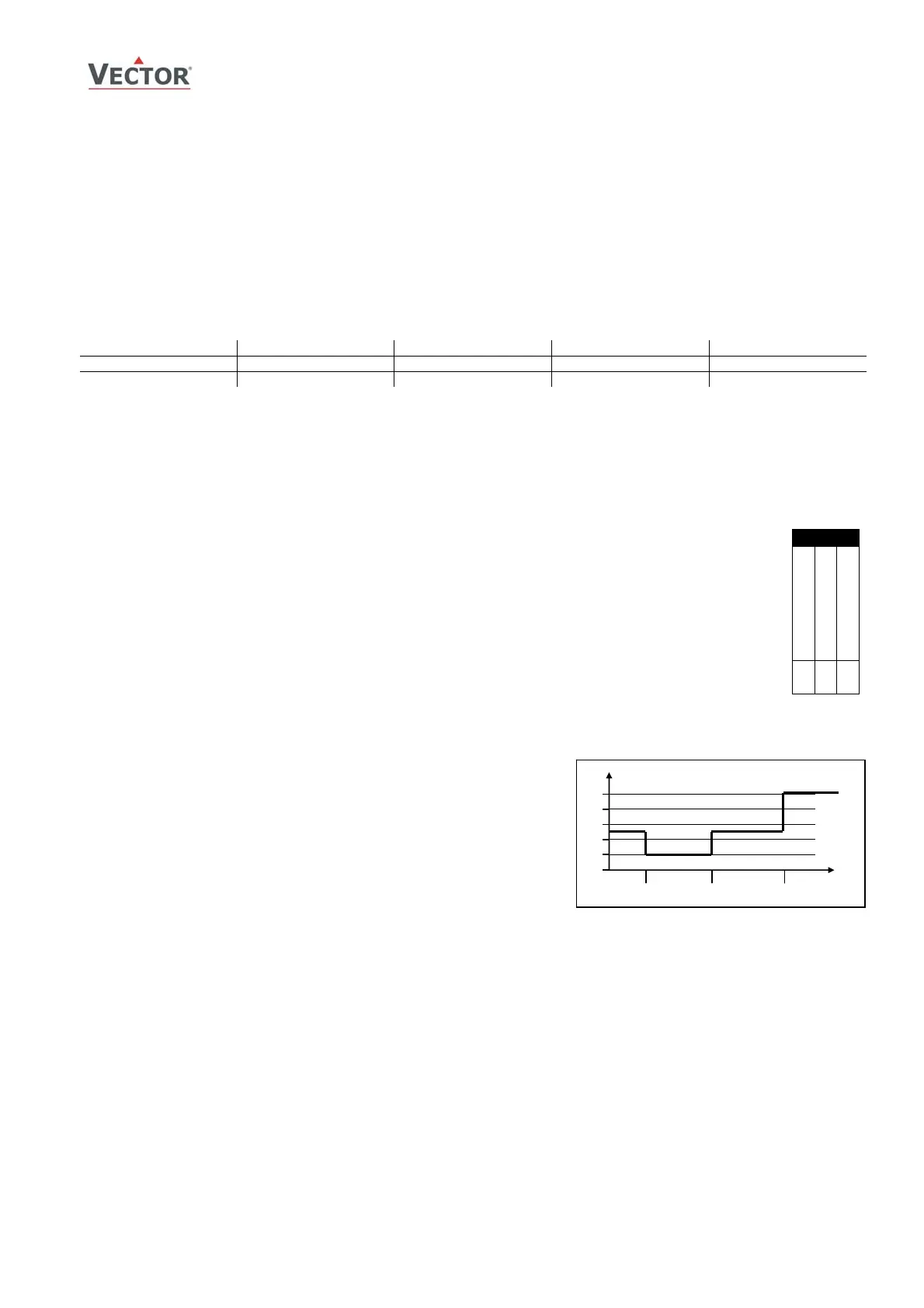
Temperature Input NTC
Placing the jumper to RT allows for passive NTC sensor to be connected as
control input. The accuracy of the temperature input is shown in the table
to the right. Specified accuracy can only be guaranteed by using a
manufacturer approved temperature sensor. For best results use Sxx-Tn10
sensors. Range limitation applies as well to the temperature inputs. By
limiting the range, the resolution may be increased.
PT1000 temperature input
The TCI-Cx-2x includes a PT1000 temperature input. The input works with a standard PT1000 probe between -50…200°C
(-58…392°F). Accuracy is within 0.5°C for the entire range. It is recommended to use a three or four wire sensor to
compensate for wire resistance.
UI
0…10V
0…20mA
RT or contact
█
0.2
0.5
1.0
ccuracy in Kelvin for
NTC Temperature Input
0 50 100
T °C
 Loading...


