TCI-C-Universal Controller
Doc: 70-00-0123, Date: 20091020 © Vector Controls GmbH Page 15
Binary Outputs
If 1d00 is in the OFF position, DO1 and DO2 are used as binary outputs. They may be used for binary sequences, as PWM
output or other special functions:
Auxiliary functions of the binary output:
Dehumidifying
(only for 4-pipe systems)
The maximum value is taken of both direct acting sequences of LP1 and LP2 (Cooling and
dehumidifying). Cooling will start to operate if the humidity gets too high, even if there is
no cooling need, thus the heating will be forced to come into play, which in turn
dehumidifies the air.
Operation State (On if
operation state is ON)
The output is ON if either comfort or standby mode are active. In energy hold off mode
(EHO) the output is off.
Output while demand on
any output
The output is ON if demand exists on any other output. The output switches on and off
with a an adjustable delay if there is no more demand. This function is usefull for fan
supported heating or cooling devices.
Output while operation
state is on and controller in
heating mode
The output is ON if either comfort or standby mode are active and the controller is in
heating mode. In energy hold off and cooling mode the output is off.
Output while operation
state is on and controller in
cooling mode
The output is ON if either comfort or standby mode are active and the controller is in
cooling mode. In energy hold off and heating mode the output is off.
Switch on delay For on demand signals: Once there is a demand the binary output will start first, once the
switch on delay has expired the other control outputs will activate. Switch on delay does
not apply to feedback signals.
Switch off delay For on demand signals: Once there is no more demand the binary output will keep running
until the switch off delay has expired. Switch off delay does not apply to feedback signals.
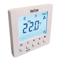
Indication of the fan symbol
By enabling this function, the fan symbol is shown on the display whenever DO1 is active.
PWM Outputs
The cycle time of the PWM signal can be set in minutes. In PWM mode the binary output will be switched on-off once per
cycle. The on and off times are calculated according to the PID output of the respective control sequence.
Set the cycle time to 0 to disable PWM and set the output to binary mode.
Floating Outputs
Enabling 1d00 changes DO1 and DO2 into a floating output for a PID loop. In this case the running time of the actuator
needs to be specified. Running time is defined as the time required for the actuator to run from fully open to fully closed
or vice versa. Actuators with a fixed running time are recommended. Once fully open or fully closed the running time for
the actuator is extended for a full run time cycle. This will allow the actuator position to be synchronized in case it has
been moved during off time or an actuator with variable running time was used.
Switching difference on floating output: Use the Switching difference parameter to reduce the switching frequency of the
actuator. The actuator will only move, if the difference to the current actuator position is larger than this parameter.
