Doc: 70-00-0158, V1.4-20220321 © Vector Controls GmbH, Switzerland Page 3
Subject to alteration
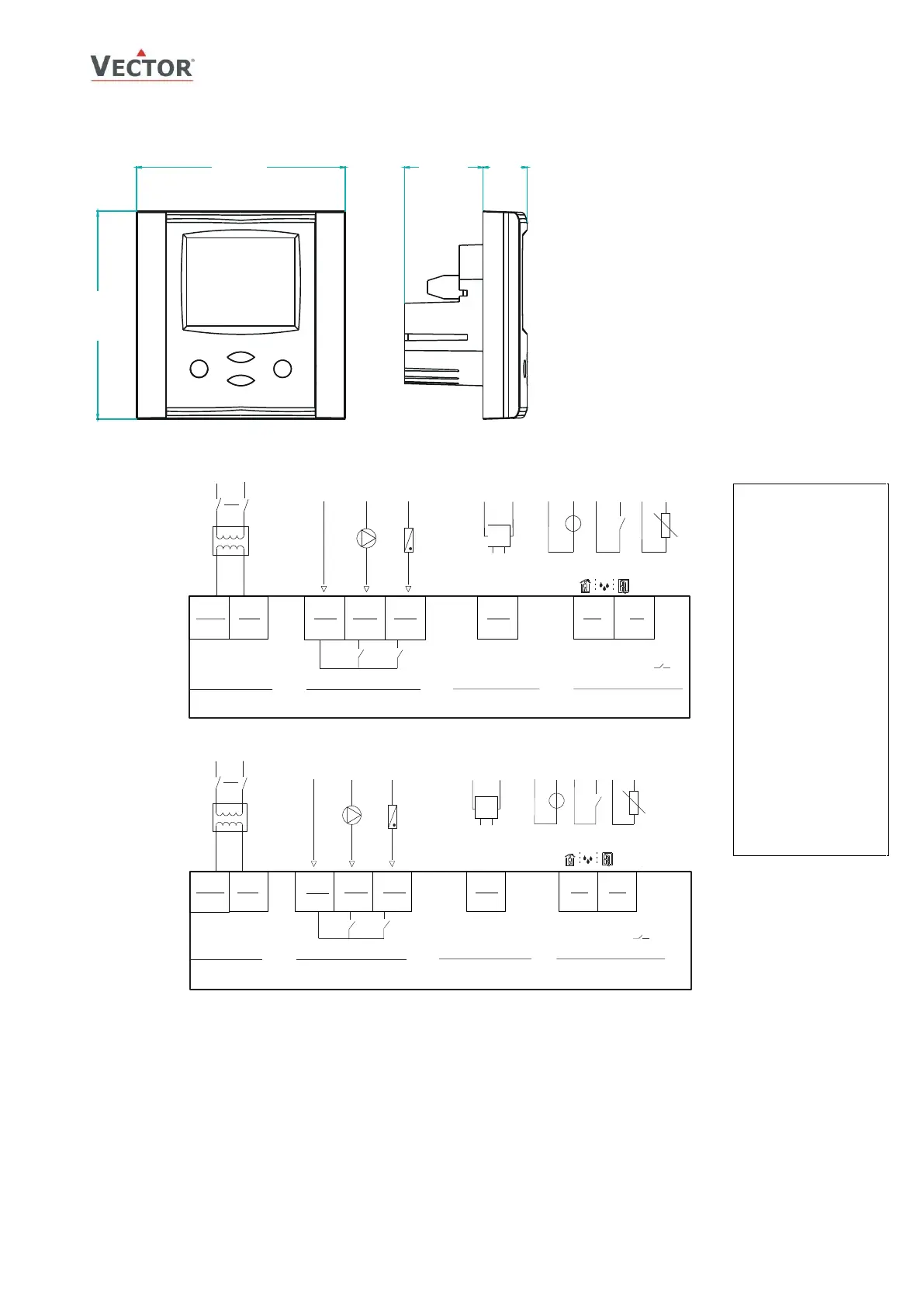
Dimensions, mm(inch)
Connection
Terminal Description
G0/M Power supply: 0V, -24VDC; common for power supply, analog in- and outputs
G Power supply: 24VAC, +24VDC
Q.. Binary outputs: Potential free relays contacts (see technical specification)
Yb1,b2 Binary output common
X
U1, u2
Universal input: NTC 10kΩ @ 25°C (77°F), 0…10 V or 0…20 mA(selectable by jumper)
Y1 Analog output: 0…10 V or 0…20 mA
*
Use copper, twisted pair, conductors only. The operating voltage must comply with the requirements for safety extra-low
voltage (SELV) as per EN 60 730. Use safety insulating transformers class II with double insulation as per EN 60 742;
they must be designed for 100% ON-time. When using several transformers in one system, the connection terminal 1
must be galvanic connected. TCI is designed for operation of AC 24 V safety extra-low voltage and is short-circuit-proof.
Supplying voltages above AC 24 V to low voltage connections may damage the controller or other devices. Connection to
voltages exceeding 42 V endangers personnel safety.
Installation
• Install the controller on an easy accessible
interior wall, approx. 1.5 m above the floor
in an area of average temperature.
• Avoid direct sunlight or other heat sources,
e.g. the area above radiators and heat
emitting equipment.
• Avoid locations behind doors, outside walls
and below or above air discharge grills and
diffusers.
• Location of mounting is less critical if
external temperature sensors are used.
• Ensure adequate air circulation to dissipate
heat generated during operation.
• Observe local regulations.
Do not mount in a wet or condensation
prone environments.

 Loading...