When 1A00 = 1configure output:
0= Heating/reverse
1= Cooling/direct
2= Heating and cooling (2 pipe)
3= Transmit setpoint
When 1A00 = 4 Manual positioning or time schedule controlled
0 = time schedule only
1 = manual positioning and by time schedule
When 1A00 = 5, select input (0= function disabled):
1= 1T, 2= 1H, 3= 1U, 4= 2U
➔ Set jumpers on the back of the controller: 0–10 VDC (default), or 0–20 mA. Further define analog outputs with
A02.Custom ranges can be created by setting minimum and maximum signal limits.
➔ A control loop, special function, digital control or analog control sequence is not active until it is assigned an output.
➔ Low and high limit alarms are defined with input parameters. With output parameters assign an
alarm to an output and select output state. The required output for each alarm can be
individually selected. Multiple alarms can be signed to one output. If one alarm is selected to
simultaneously activate and deactivate an output, the one to de-activate has precedence.
➔ With manual positioning (1A00=4) position the output by time schedule or directly in 0.5%
steps. Setting 1A01 to 0 will disable manual positioning. The output will then only be controlled by time schedule.
➔ With dehumidifying (1A00=3) the maximum value is taken of cooling and dehumidifying. When the humidity is too
high, cooling will continue to operate, even without a demand for cooling, to dehumidify the air and heating will
activate to maintain comfort.
➔ Input values of inputs and set points of control loops may be transmitted on the analog outputs.
➔ Minimum or maximum limits of output signals may be reversed. This allows to create a control option for
example of 6-way valves where the following conditions are required: 0% full cooling, 50% no cooling or heating,
100% full heating. This is achieved by setting 1A05 = 50%, 1A06 = 0%, 1A03 = 50% and 1A04 = 100%.
While one sequence is reversed and the other is direct, the output will remain in OFF mode at the percentage defined
with the last active minimum sequence.
Note: Alarm values will not be affected by minimum or maximum limits.
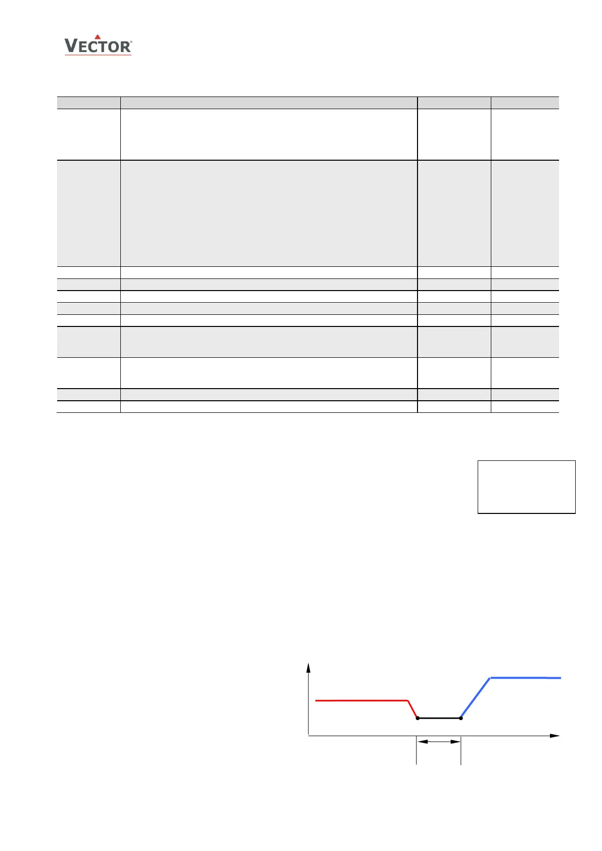
➔ For VAV Function individual minimum and
maximum limits may be assigned for cooling and
heating. In VAV applications maximum cooling
output matches the maximum air volume the
VAV box is set to deliver. As demand for airflow
in cooling mode decreases, airflow dwindles until
it reaches minimum cooling output (1A05). This
minimum will be based on the airflow needed at
design cooling and is typically 10% to 15% of
maximum cooling airflow. When this minimum is
reached the system is in dead-band – neither
heating nor cooling. Minimum airflow in heating
mode is set with 1A03. As the system moves into heating mode, heating airflow increases until it reaches the
maximum heating output (1A04), typically 30 to 50% of maximum cooling airflow.

 Loading...