2 Vac Sensor Installation Field Assembling Vac Sensor/Vac Float modules
2-4
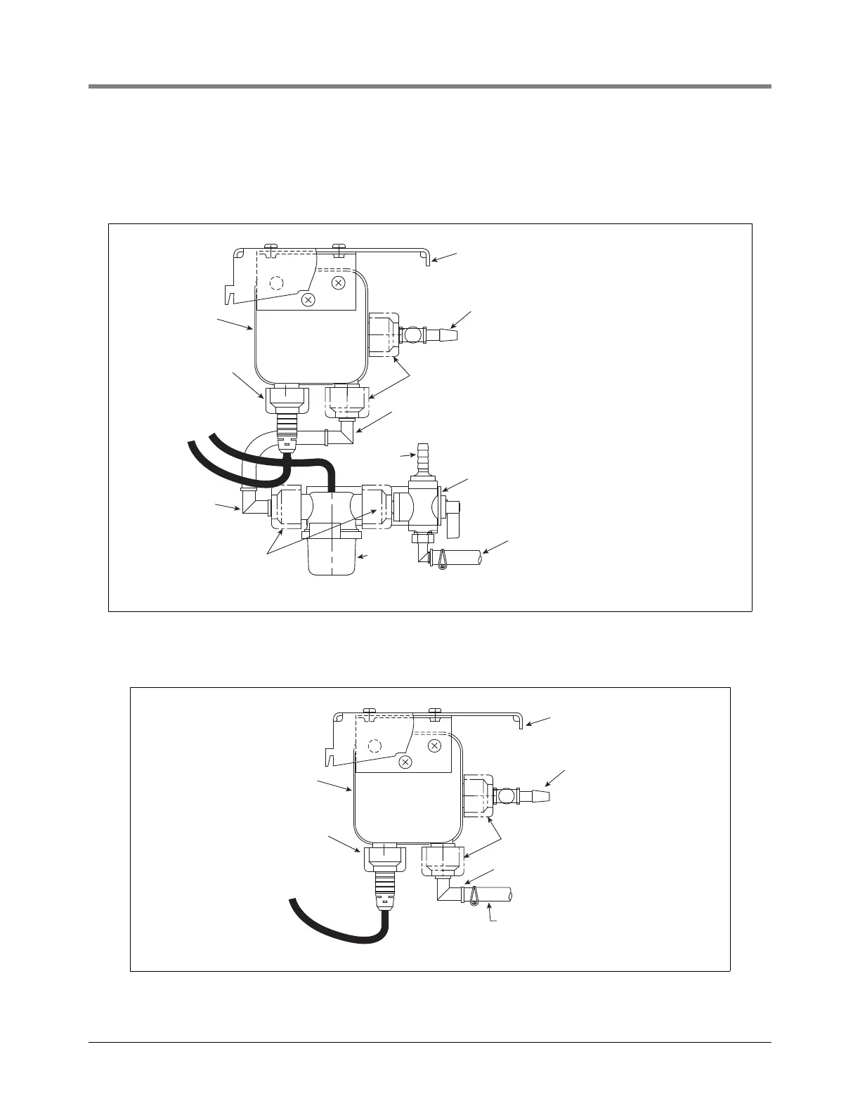
toward the other tees and one end points out at you then insert the inlet end into the bushing. Measure and cut
a piece of the tubing approximately 1-3/4” (44.5mm) long to connect each of the tees and elbow as shown in
Figure 2-6. Once the tubing pieces are cut, remove the barbed elbows and tees to push on the tubing pieces,
then reinsert this connected assembly back into the Vac Sensor bushings and tighten the nuts.
Figure 2-4.- Vac Sensor/Vac Float Tubing Connections
Figure 2-5.- Vac Sensor /Tank Interstice Tubing Connections
Vac
float
Vac Sensor
Cable connector
(TLS port)
3-way ball valve - Valve handle shown
in operating position (down). To vent
monitored interstice rotate handle up.
Vent port
Tapered bushing/nut
Tapered bushing/nut
Tubing connects to interstitial
space being monitored
Cable pair to
junction box
Barbed elbow (VAC TEST port)
Barbed elbow
Barbed tee
(STP SIPHON port)
Front of housing
Vac Sensor
Cable connector (TLS port)
Tapered bushing/nut
Tubing connects to Tank Interstice
3-way valve
Cable pair to
junction box
vacsensors/fig6a.eps
Barbed elbow (VAC TEST port)
Barbed tee
(STP SIPHON port)
Front of housing

 Loading...