6-7
6 Vac System Testing - TLS-450PLUS Console Running a Manual Test
screen (below) and place each of the monitored Vac Sensors in EVAC HOLD (ref. Vacuum Sensor System
Troubleshooting Manual, P/N 577013-873).
3. At the 3-way ball valve connected to the tank’s interstitial riser cap, connect the external vacuum source to the
valve’s top barbed fitting. Rotate the valve handle to its up position and pull a vacuum down to -8 psi (-55.1
kPa), or if a relief valve is present, down to 1 psi (6.89kPa) above the relief valve’s opening pressure (e.g., if
relief valve opens at -7 psi [-48.26 kPa], pull the vacuum down to -6 psi [-41.36kPa]). When the desired
vacuum is attained, rotate the valve handle to its down position. Remove the external source from the valve’s
upper barbed fitting.
4. If necessary, repeat this procedure for the product line’s interstitial space, the vapor line’s interstitial space and
the double-wall containment sump’s interstitial space.
5. With all of the monitored interstitial spaces under vacuum, at the TLS Console, stop the EVAC HOLD for each
Vac Sensor. After a minimum wait of 12 minutes, monitor the Leak Rate and Time to No Vac display for each
Vac Sensor. Record the displayed values for each of the containment sump’s Vac Sensor in the chart in
Appendix A.
As a general guideline, the Time to No Vac should ideally be 100 hours, and should not be less than 24 hours.
Also, a Leak Rate greater than 22.4 gph (84.79 litre) will generate a Vacuum Warning. Both of these diagnos-
tics are indicators of whether the system has a significant vacuum leak.
If either diagnostic exceeds the guideline, the source of the leak should be corrected before the system is start-
ed up. Once the leak(s) is corrected, repeat steps 2-5.
6. When the monitored interstitial spaces under vacuum are within normal operating limits as described in Step 5,
fill the tank.
7. Once the tank is full, restore power to the pump.
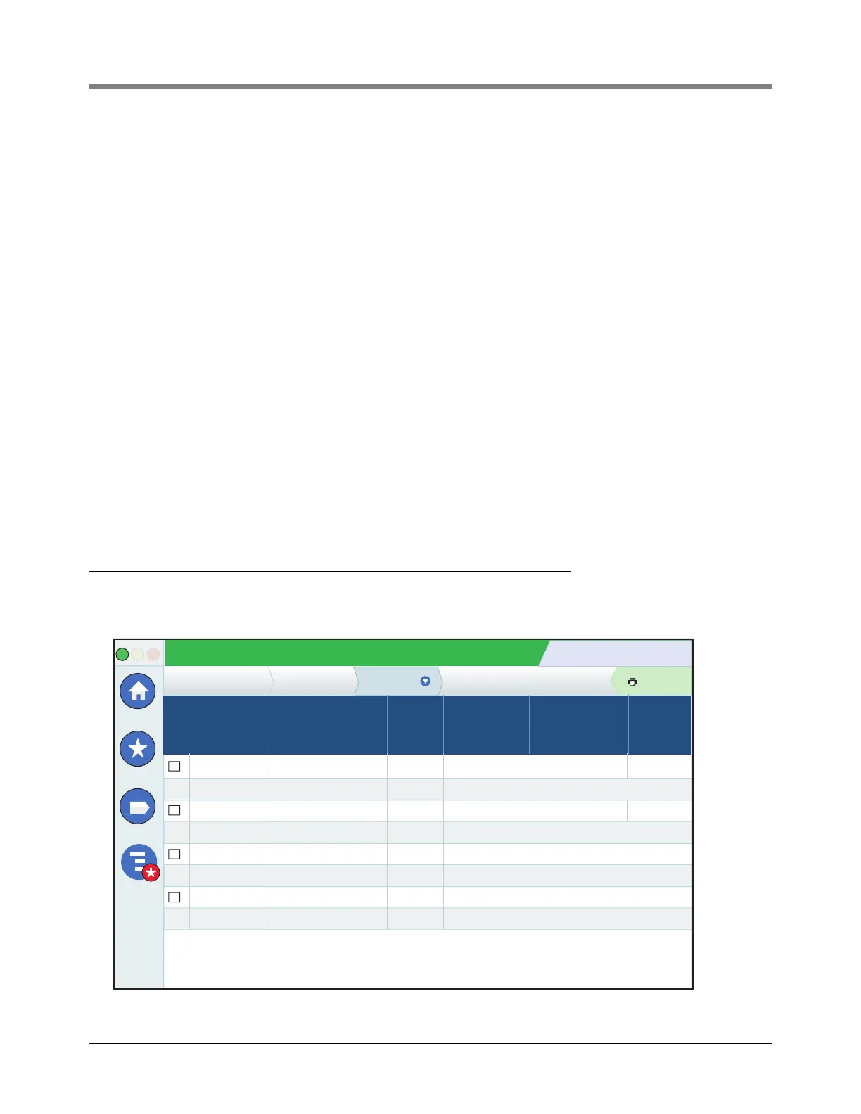
Running a Manual Test
1. Go to Menu>Diagnostics>Vac Sensor>Status screen. Select the box at the beginning of each row to
select an individual Vac Sensor.
System Status
10/16/2018 08:51 AM
0 Warning(s)
0 Alarms(s)
Print (0)
Actions
Diagnostics
Vs 1: Vac1 EVAC PENDING
VACUUM OK
VACUUM OK
VACUUM OK
-5.853
-9.000
-8.000
-8.000
9.998
0.000
0.000
0.000
Closed
Closed
Closed
Closed
3 : 3
100 : 0
100 : 0
100 : 0
Vac Sensor Status
Vac Sensor Evac State Valve
Pressure
(Comp)
[psi]
Time To
No Vac
HHHH:MM
Leak Rate
[gph]
Vs 2: Vac2
Vs 3: Vac3
Vs 4: Vac4
10/16/2018 08:51 AM
10/16/2018 08:50 AM
10/16/2018 08:51 AM
10/16/2018 08:50 AM
Home
Favorites
Menu

 Loading...