D-302754 5
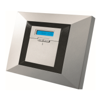
Back unit
Mark 4 drilling points on mounting surface
3
1
Release
screws
4
Drill 4 holes and insert wall anchors
5
Fasten the back unit with 4 screws
Figure 3.1 – Back Unit Mounting
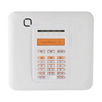
Connect telephone cable to SET connector and telephone line cable to LINE connector (through the desired wiring cable entry).
PHONE WIRING
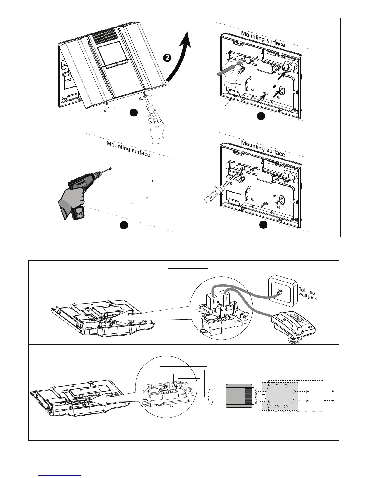
PHONE WIRING IN NORTH AMERICA
RJ-31X
CORD
HOUSE
PHONES
RJ-31X
8-POSITION
RJ-31X PLUG
BROWN
GRAY
GRN
RED
LINE
FROM
STREET
1
23
4
5
6
7
RJ-31X JACK
GRAY
BROWN
GREEN
RED
Phone wiring in the UK: Line terminals must be connected to pins 2 and 5 of the wall jack.
For all installations: If DSL service is present on the phone line, you must route the phone line through a DSL filter (refer
to MESSAGE TO THE INSTALLER on page 2 for further details).
 Loading...