34 AB Volvo Penta / Diesel Engine TAMD71B
8 Technical description
Lubrication system
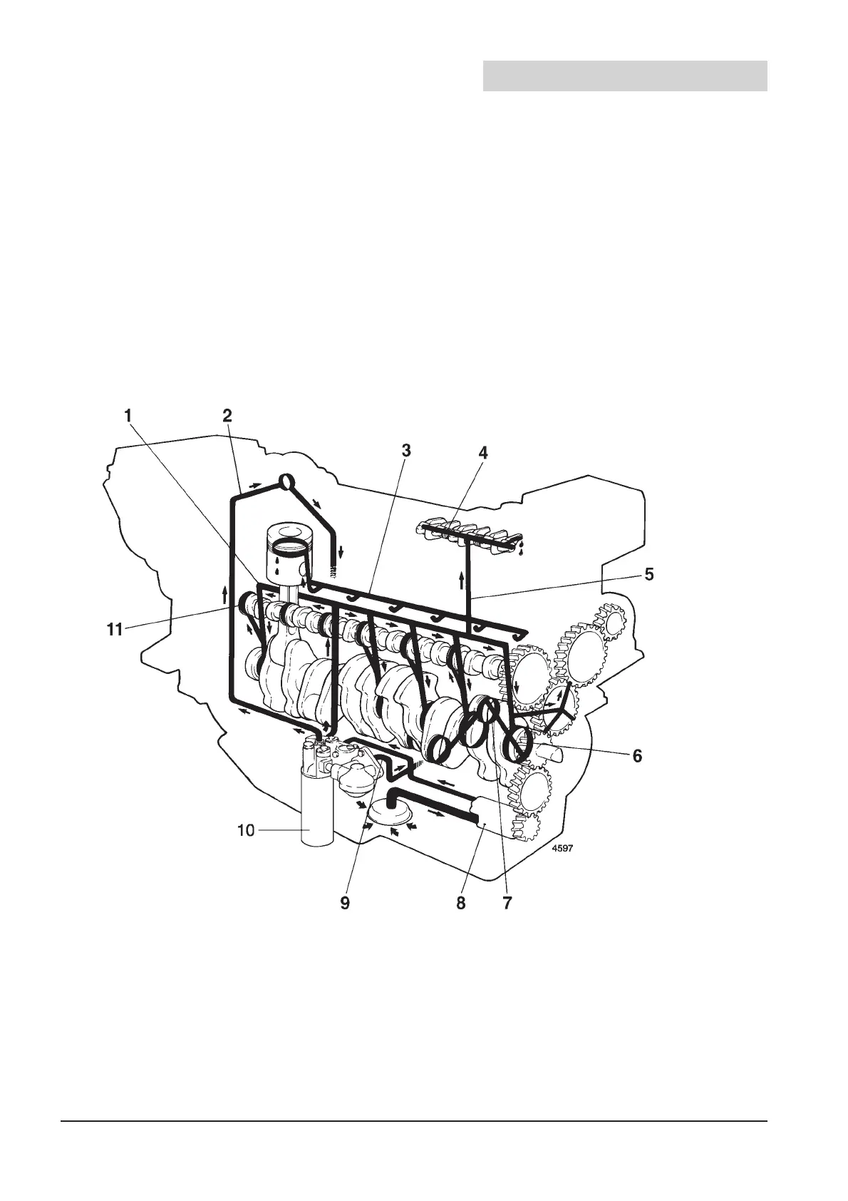
These engines have a forced lubrication system and piston cooling (see “Pistons” in chap. 7.5). The
oil pump is of the gear-wheel type and is located at the front of the oil sump. This pump is driven by
the engine’s timing gears.
The oil pump sucks oil up from the oil sump and then forces it out into two main channels in the cylin-
der block (see Fig. 8.2 Basic diagram). The oil passes through the lubricating oil filter and then on into
the engine’s oil channels for the forced lubrication of the engine, injection pump and turbocharger. The
oil also passes through via the piston cooling valve.
1. Main oil gallery (lubricating oil)
2. Pressure line to turbocharger
3. Main oil gallery (piston-cooling oil)
4. Rocker assembly
5. Oil gallery to rocker assembly
6. Main bearings
7. Big-end bearings
8. Oil pump
9. Oil to oil cooler and piston cooling
10. Engine oil filter (full flow type)
11. Camshaft bearings
Fig. 8.1 Lubrication system TAMD71B
8.1 Lubrication system, diagram
 Loading...
