51
AB Volvo Penta / Diesel Engine TAMD71B
11 Technical description
Electrical system
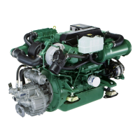
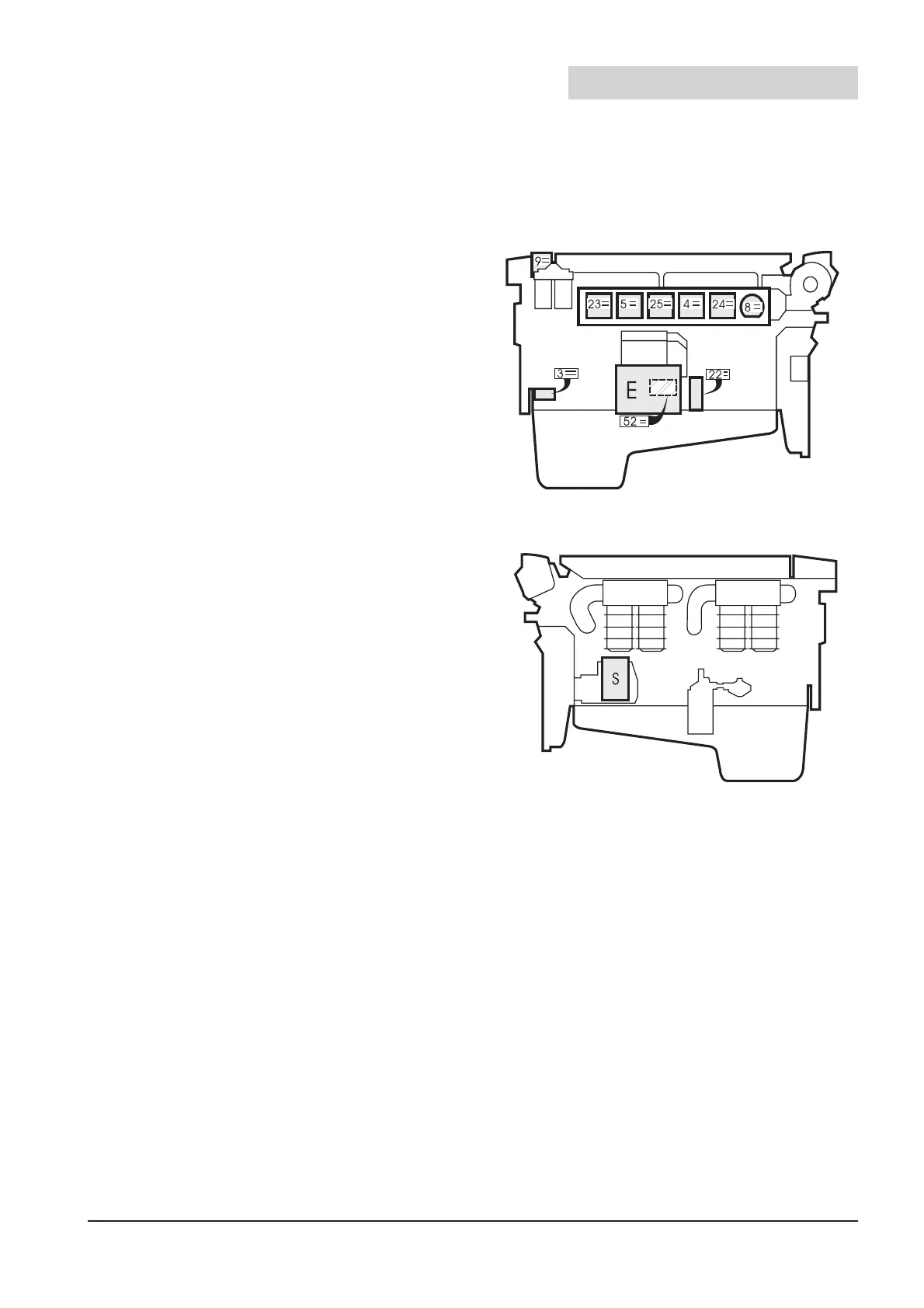
Figure 11.1 TAMD 71B, turboside
Figure 11.2 TAMD 71B, not turboside
components
Pos. Marking
3 TACHO SENDER
4 OIL PRESSURE AUTO STOP
5 WATER TEMP. AUTO STOP
8 OIL PRESSURE SENDER
9 WATER TEMP. SENDER
22 FUEL LEAKAGE ALARM
23 OIL TEMP. ALARM
24 OIL PRESSURE ALARM
25 WATER TEMP. ALARM
52 EMERGENCY STOP
E ELECTRICAL BOX
S STARTER MOTOR PROTECTION
For further information on electrical components
see
“Control and Monitoring system, Function
and installation”
Publ. No 7738014-5.
11.2 Starter motor
The starter motor is mounted on the flywheel
casing on the starboard side of the engine.
When the starter motor is engaged, a drive on
the starter motor’s rotor shaft is moved in an axi-
al direction so that it engages with a spur ring on
the engine’s flywheel. The drive’s axial move-
ment and the engagement of the starter motor
are controled by a control solenoid on the starter
motor.
The starter motor’s control solenoid is engaged
in turn via the starter relay when the ignition key
is held in position III. For start by Control Unit –
500, see chapter 5.2.
11.1 Location of electrical
 Loading...