44 AB Volvo Penta / Diesel Engine TAMD71B
10 Technical description
Cooling system
These engines are fluid-cooled and have a closed circuit cooling system. The system has two circuits.
In the inner circuit (the freshwater system), coolant is pumped around by a centrifugal-type coolant
pump (circulation pump).
From the coolant pump, the coolant is pumped out into a distribution channel in the cylinder block and
conveyed around the cylinder liners and on up through the cylinder heads.
From each cylinder head and from the turbocharger’s turbine housing, the coolant is fed back to the
thermostat housing, where a thermostat regulates the coolant temperature. Coolant from the engine’s
oil cooler is also fed to the thermostat housing.
While the coolant is cold, the thermostat shuts off the flow to the heat exchanger. The coolant then
passes through a by-pass line beneath the thermostat and directly back to the pump’s suction side.
When the coolant temperature has risen to a certain value, the thermostat opens and allows coolant
to pass to the heat exchanger and the by-pass line closes.
In the heat exchanger, heat from the coolant is transferred to the raw water before the coolant is
sucked back into the coolant pump.
Large amounts of heat are also removed by the lubricating oil, which channels off the heat to the
freshwater system via the oil cooler. The lubricating oil is also used to dissipate heat from the pistons
in the engine (see “Pistons” in chap. 7.5).
The cooling system may operate with a small amount of overpressure. The risk of boiling is thereby
reduced if the temperature is high. If the pressure is higher than normal, a pressure valve in the filler
cap opens.
The flow in the raw water system is maintained by a gear-wheel driven impeller (blade-type) pump
which is located at the front of the engine. The raw water passes through the engine’s heat
exchanger(s) and charge air cooler(s).
It is important to check the condition of the zinc anode(s) according to the maintenance schedule to
prevent corrosion damage.
The engine may have a separate expansion tank as an accessory.
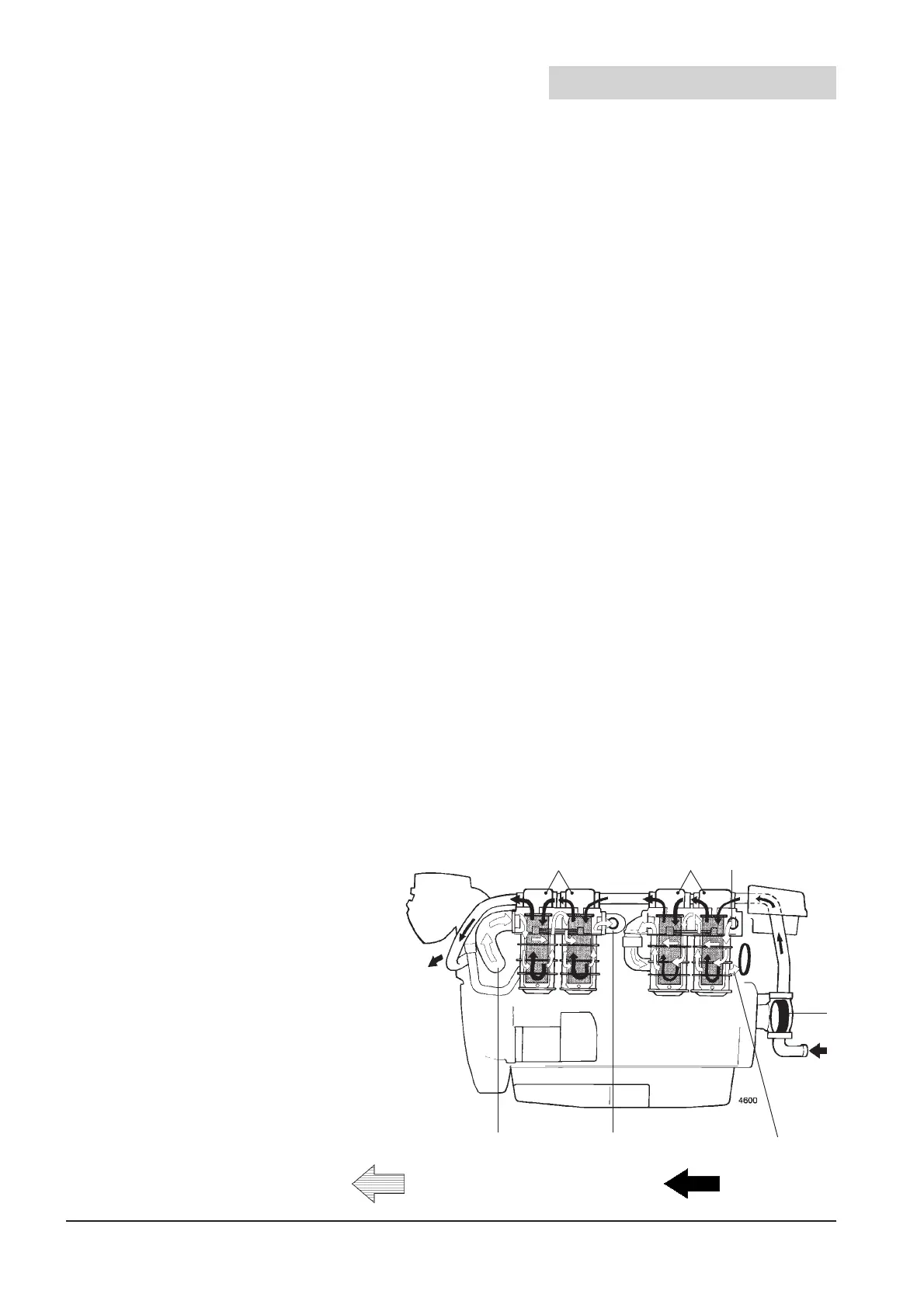
Fig. 10.1 Flow through heat exchanger and charge air cooler (CAC) Coolant pump and thermostat
1. Raw water inlet
2. Raw water pump
3. Freshwater from engine thermostat housing
4. Heat exchangers
5. Charge Air Coolers (CAC)
6. Sea water outlet
7. Charge air from turbocharger
8. Cooled charge air to the engine intake manifold
9. Freshwater to the engine coolant pump, suction side
7 8 9
543
6
2
1
= Charge air or freshwater = Raw water
 Loading...
