2A-7
G50/G70/G85 MAINTENANCE 2A
L0
Y
L3L2
4
24
23
L1
86
87
85
R
B+
B+
D+
30
G/Y
N.C.
1
2
10
N.O.
R
B+
5
9
8
7
12
2
1
5
Y
8
7
3
1
3
5
6
7
9
12
8
11
G/Y
O
B
W
W/B
Y
W
B
Cl
R
Gr
V
14
13
20
B
Cl
Sh
W/B
Y
B
W/V
O
V
15
16
18
19
Gr
R
R
R
21
22
V
Gr
R
B
B
24
R
R
Y
R
Gr
V
23
R
R
O
Y
B
B
B
Y
2
10
17
B
W
R
B
AC
AC
R
Y
Y
Y
3
4
Y
B
W
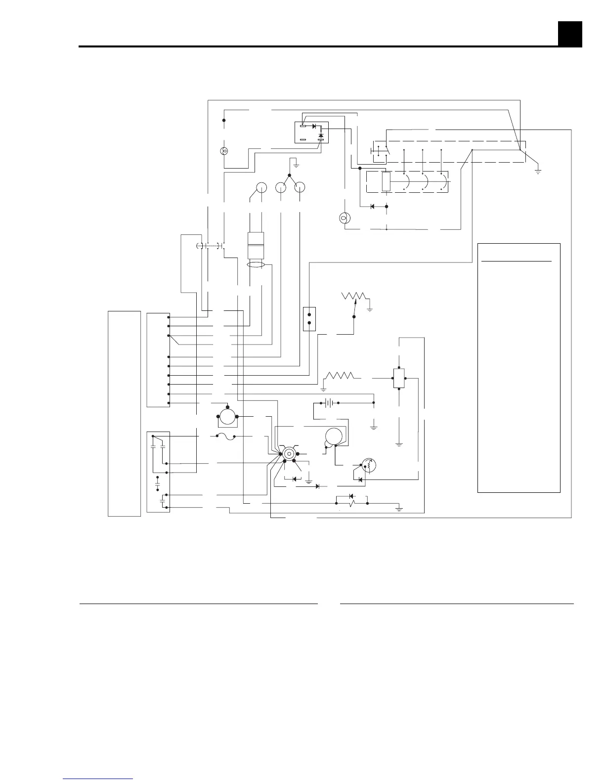
Ref. Description
1. Emergency Stop LED
2. Safetyinterock switch
3. Mechanical lugs
4. Magnetic pickup
5. Oil pressure sender
6. Water temperature sender
7. Main circuit breaker
8. Shunt
9. Emergency Stop switch
10. Safety interlock switch LED
11. Engine control module
12. Plug 1 - engine sender inputs
Ref. Description
13. Remote start contacts
14. Fuel level sender
15. Intake heater
16. Intake heater relay
17. Plug 2 - engine start outputs
18. Run/off/auto switch
19. Battery
20. 10A fuse
21. Starter relay
22. Starter
23. Alternator
24. Fuel solenoid
WIRE COLORS
B - BLACK
Br - BROWN
L - BLUE
LL - LIGHT BLUE
R - RED
P - PINK
V - VIOLET
O - ORANGE
Y - YELLOW
G - GREEN
Gr - GRAY
W - WHITE
Cl - CLEAR
Sh - SHIELD
2.11 Engine Wiring
1028SD99
 Loading...