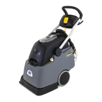
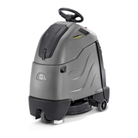
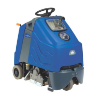
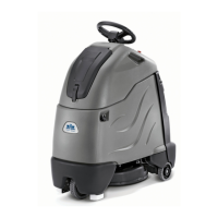
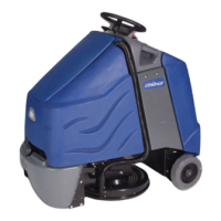
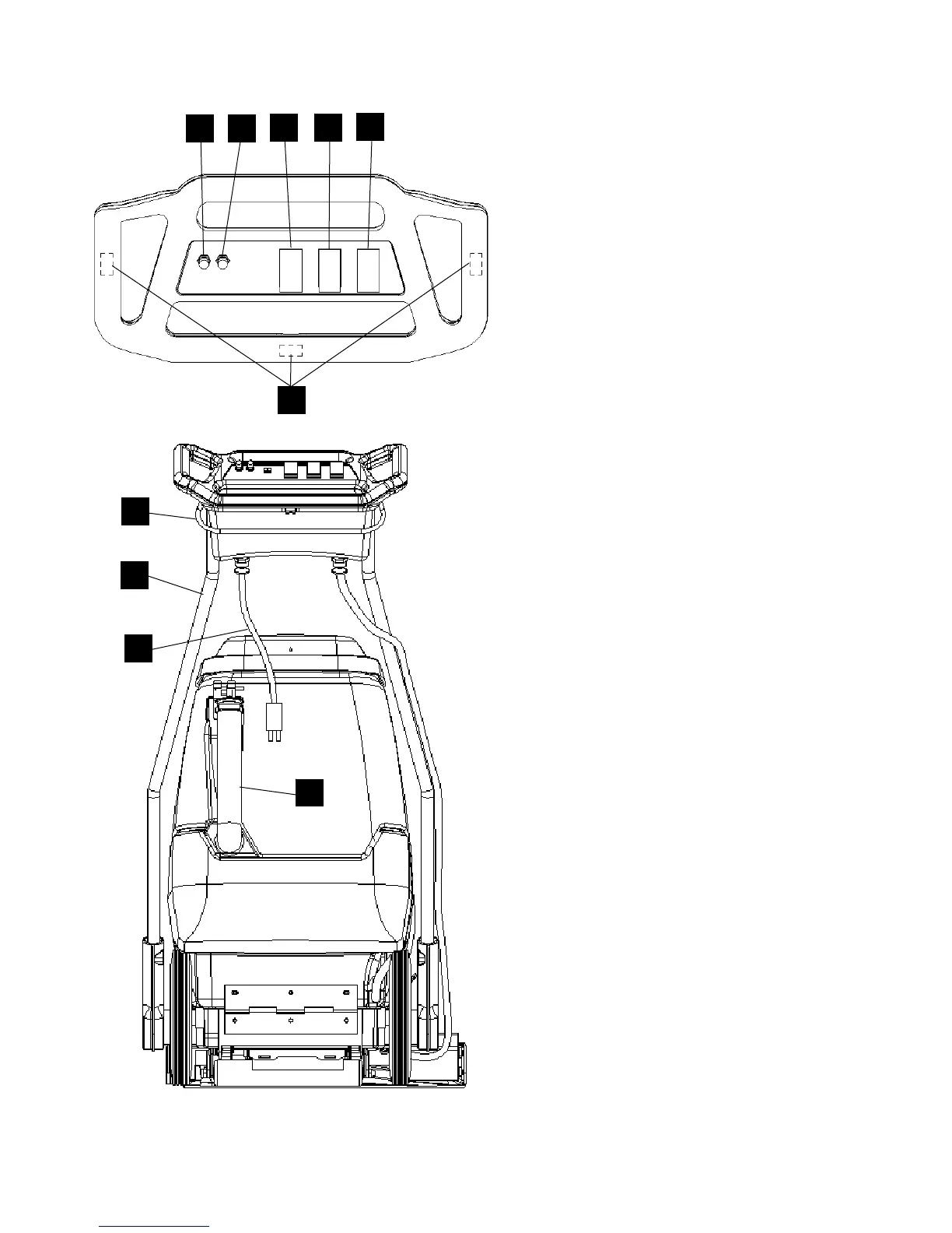
CONTROLS/COMPONENT LOCATIONS
CLIPPER 86038240
3-2
1. Main Handle. Used to pull and maneuver
machine.
2. Handle Adjustment. Used to adjust height of
handle, and allow machine to be used in “PUSH”
or “PULL orientation.
3. Electrical Cord.
4. Solution Switch. Turns on pump. Continuous
position (bottom) activates electro-valve to
dispense solution to floor through jets.
Intermittent position (up) requires operator to
depress 1 of 3 trigger switches to dispense
solution. Center position is off.
5. Brush Motor Switch. Turns on brush motor.
6. Vacuum Motor Switch. Turns on vacuum
motor.
7. Trigger Switches. Activates electro-valve to
dispense solution to floor through jets when
solution switch is in the intermittent position.
8. Brush Motor Circuit Breaker. 6 amp. Breaker
protecting brush motor.
9. Vacuum Motor Circuit Breaker. 15 amp.
Breaker protecting vacuum motor.
10. Recovery Dump Hose. Facilitates draining
dirty cleaning solution.
3
1
10
2
5
8
9
4
6
7
 Loading...