53061809_1210
Installation / Electrical work
Jointhepowersupplycabletotheplugsupplied.Inserttheplug
into the marked-up location in the plug-in connector strip, and
securethecablewithitsstrainrelief.Routethecablethroughthe
boilerbackcutout.
Power supply connection
Electrical work
Mains230V
LP=Primarypump
A1=Programmableoutput
KKP=Boilercircuitpump
eBUS
E1=Programmableinput
SF=Cylindersensor
AF=Outsidetemp.sensor
Wheninstallingthiscontrolunitensurethatsensorcapillariesare
neitherkinkednortwisted.
Never route on-site sensor and remote control leads / cables
togetherwithmainspowercables.
Implement the electrical wiring in accordance with the wiring
diagram.
Opentherearcontrolunitcoverafterreleasingbothscrews.
Burner supply cable
Guideitthroughtheapertureinthecontrolunitbracket(l.h./r.h.),
subjecttothesidetowhichtheboilerdooropens.
Boiler sensor
Insertintoanyopeningoftheboilersensorwell.
High limit safety cut-out
Insert sensor capillaries into any opening in the boiler sensor
well.
Earth terminal
Insertintothecontrolunitpanel.
Thermometer for boiler water temperature display
Insertintoanyopeningoftheboilersensorwell.
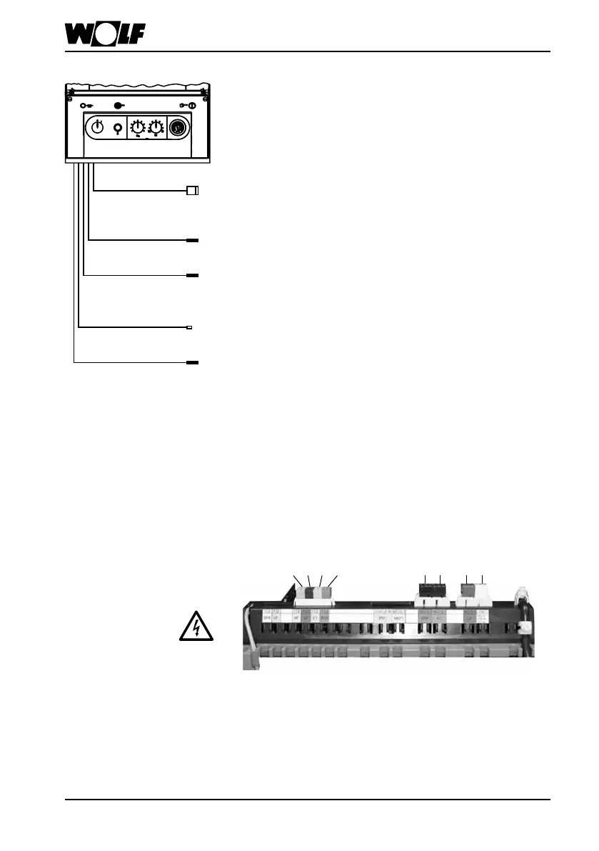
Installation
Burnersupplycable
Boilersensor
Highlimitsafety
cut-out
Earthterminal
Thermometer
Insertallplugsthatarenotusedintotheplug-instrip.Observe
thecolourcoding.
Info
 Loading...