Setting the Tool
Note:
Thistoolisaccuratelyadjustedbeforeshippingfromthe
factory. Check the following accuracy and readjust if nec-
essaryinordertoobtainthebestresultsinoperation.
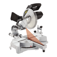
Adjusting the Bevel Stops at 90° and 45° (Fig. 3)
• Loosen the Bevel Lock Handle and move the cutting
headallthewaytotherightandtightentheBevelLock
Handle 1.
• Useasquaretosetthebladeat90°tothetable.
• Ifanadjustmentisnecessary,loosenthelocknut2and
adjustthebolt3usingthesuppliedwrenchsothatthe
blade is 90° to the table.
• Tightenthelocknut.
• Adjustthebevel indicator 4 to the 0 mark using the
screw.
• Toadjustthe45°stop,followthesameprocedureas
the 90° but move the cutting head to the left and use
the lock nut 2 and bolt 3.
Adjusting the Fence
• Lowerthecuttingheadandpushinthelockpin.Make
surethetableisin0mitreposition.
• Placeacombinationsquareagainstthefenceandnext
to the saw blade.
• If the blade does not contact the square, loosen the
screws .
• Adjustthefencesothatthefencehasfullcontactwith
the square. Tighten the screws.
Connecting to the Power Supply
Checkthat thepowersupplyandoutletusedareinac-
cordance with your mitre saw. Have a look at the rating
plate of the motor or the rating on the mitre saw. Any
changesshouldalwaysbecarriedoutbyaqualiedelec-
trician.
This is a double insulated tool which eliminates the need
foranearthedpowersupplysystem.
WARNING! Avoid contact with the terminals on the plug when
installing (removing) the plug to (from) the power supply out-
let. Contact will cause a severe electrical shock.
Using an Extension Lead
The use of any extension lead will cause some loss of
power.To keep this toaminimumandtopreventover-
heatingandpossiblemotorburnout,askadvicefroma
qualiedelectriciantodeterminetheminimumwiresize
of the extension lead.
Theextensionleadshouldbeequippedwithanearthed
type plug that ts the power supply outlet at one end,
andwithanearthedtypesocketthattstheplugofthis
machine at the other end.
Réglage de la scie
N. B. :
Lascie aétéajustéeavecprécisionenusineavantson
expédition.Pourobtenirlesmeilleursrésultats,faireles
véricationssuivantesdelaprécisionetajusterdenou-
veau au besoin.
Réglage des angles de chanfrein de 90° et 45° (Fig. 3)
• Desserrerlamanettedeblocagedechanfreinetpous-
serlatêtedecoupeversladroiteaussiloinqu’ellepeut
aller,puisresserrerlamanettedeblocage1.
• Al’aided’uneéquerre,ajusterlalamepourlamettre
perpendiculaireauplateau.
• Siunajustements’impose,desserrerlecontreécrou2
etajusterleboulon3àl’aidedelacléfournieàcette
n,defaçonquelalamesoitperpendiculaireaupla-
teau.
• Serrerlecontreécrou.
• Amenerl’indicateurdechanfrein4àlagraduation0en
tournant la vis.
• Pourleréglageà45°,procéderdelamêmefaçon,mais
pousserlatêtedecoupeverslagauche et utiliser le
contreécrou2etleboulon3.
Adjustement du guide
• Abaisserlatêtedecoupeetlabloqueraveclagoupille
desécurité.S’assurerqueleplateauestdanslaposi-
tion d’onglet 0.
• Placerl’undesbrasd’uneéquerrecombinéecontrele
guide et l’autre contre la lame de scie.
• Silalamenetouchepasl’équerre,desserrerlesvis.
• Ajusterleguidedefaçonqu’iltouchel’équerretoutau
long. Serrer les vis.
Branchement de la scie
S’assurerquelecourantetlapriseutiliséecorrespondent
àcedontlascieabesoin.Voirlesspécicationsqui-
gurentsurlaplaquesignalétiquedumoteuroucellesqui
gurentsurlascie.Toutchangementdoitêtreeffectué
parunélectricienqualié.
Ayantunedoubleépaisseurd’isolement,lascien’apas
besoin d’une alimentation mise à la terre.
ATTENTION : Eviter tout contact avec les pointes de la fiche
quand on l’enfiche dans la prise de courant ou qu’on l’en re-
tire. Tout contact causera un choc électrique dangereux.
Emploi d’une rallonge
L’emploi d’une rallonge entraîne automatiquement une
certainepertedecourant.Pourminimisercetteperteet
empêcherlemoteurdes’échaufferetdegriller,deman-
deràunélectricienqualiéquelcalibreminimaldella
rallonge doit avoir.
Larallongedoitêtremunie,àuneextrémité,d’uneche
mâleavecmiseàlaterre,quis’enchedanslaprisede
courantet,àl’autreextrémité,d’unechefemelleavec
miseàlaterre,quis’enchedanslascie.
Montage de la scie
 Loading...