Contents
1.
Installation
Reg
ulat
ions
Page2
9.
Electri
cal
Page
9
2.
General
Information
Page2
10.
In
stallation
Page
12
3.
Techn
ical
Data
Pag
e4
11.
Commissioning
Page
16
4. S
iting
the
Appliance
Pages
1
2.
l
ntructions
to
the
User
Page
19
5.
Flue
Terminal
Posit
ion
Pa
ge7
13.
Inspection
and
Servicing
Page
20
6.
Air
Suppl
y
Page
7
14
.
Replacement
of
Parts
Page
23
7.
Sea
l
ed
Sy
stem
Page
7
15.
Short
Pa
rts
List
Page
30
8.
Domestic
Hot
Water
Page
9
16.
Operational
Flow
Diag
r
ams
Page
32
1
7.
Fault
Find
ing
Page
34
1 . Installation Regulations
1.1
Ga
s Safety (Installation
and
Use)
Regulations 1 984:·
All
gas
ap
pliances
must
be installed by a competent person in accordance
with
the
above regulations. Failure
to
insta
ll
appliances
co
rrectly
could lead
to
prosecution.
1 .2 The manufacturers
no
tes
must
not
be
taken
,in a
ny
way,
as
overriding statutory obligations.
1.3
Th
e compliance with a Brit
is
h Standard does not, of itse
lf
, con·
fer immuni
ty
from l
ega
l obligations.
In
particular the installation of
this appliance
mu
st
be
in
accordance with
the
relev
ant
re
quire·
me
nt
s of
the
Ga
s Safety (Installation and Use) Regulations 1 9
84
(as
amended),
current
lEE
Wiring
Re
g
ulat
io
ns
, local Building
Regulations, Building Standards (Scotla
nd)
(Consolidation), by
e·
laws
of the local
Water Company
and
H
ea
lth
and
Safety Docu
-m
ent
No
.
635
( Electricity
at
Wo
rk Regulations 1989).
It
should
be
in
accor-
dance with t
he
rele
vant
recommendations of the following British
Standards.
BS
6798:1987 Specification for installation of gas
fi
red
hot
water
boilers of rated input
not
exceeding 60
kW
BS
5449
:
1990
Central Heating
for
Domestic Prem
is
es
BS
5546:1990 Installation of
gas
hot
wa
te
r supplies f
or
domestic
purposes
BS 5440:1 :
199
0
Flu
es
and
ventilation for gas appliances
of
rated
input
not
exceeding
60
k
W:
Flues
BS
5440:2:1989
Flu
es
and
ventilation for
gas
appliances of ra
ted
inp
ut
not
exceeding 60kW:
Air
Supply
BS
6891 :1
988
Installation of low pressure
gas
pipework installa-
tions
up
to
28
mm
(R
1)
1
.4
To
ensure
that
the
installation
will
perform to
the
highe
st
stan
-
dards,
the
system and co
mpon
ents
should con
fo
rm to any
other
rele
vant
British Sta
nd
ards in addition to
tho
se
mentioned
in
the
instructions.
2.
General Information
2.1 This
sec
tion contains a s
um
mary
of
esse
ntial infor
mat
ion.
Refer
to
the
appropriate main sect
io
ns for more information.
2.2
This appliance
is
not
suitable for exte
rn
al installation.
2.3 The appliance controls are
set
to
provide a maximum
output
of 35.17kW for
the
domestic
hot
water
and
can
be
reset to satisfy
a central heating
lo
ad
of
up
to
25kW. The appliance leaves t
he
fac-
tory
set
to
sat
isfy a central heati
ng
load of 1
SkW.
2.4
PRINCIPLE
APPLIANCE
COMPONENTS
.
The appliance c
ompr
ises
the
follo
wing:
A low
th
e
rm
al
ca
pacity
gas
to water heat exchange
r.
A Water
to
Water
heat
exchanger
to
provide domestic
hot
water.
Separate circulating
pumps
for domestic
hot
water
and
for central
heating.
A drain point.
2
Full
y
modu
lating controls
in
the
central
hea
ting
and
domestic
hot
water
mo
des of
opera
tion.
An
expansion vessel, pressure gauge
and
pressure relief valve.
A by-pass for
the
heating system.
Temperature
and
wate
r pressure safe
ty
cut
-o
ut controls.
A variab
le
speed
fan.
A water flow regulator.
An
optional extra flue kit to provide for flue lengt
hs
up
to 2 metres.
A facia
mounted
programmer is available
as
an
opt
ional extra.
2.5
ELECTRICAL
SUPPLY.
Mains supply:
240V-
50Hz, 3
40
watts
. External Fuse
3A.
Internal
Fuses
F2A
(20 mm).
A supply failure
will
stop
the
ap
pliance operating. The appliance
will automatically return to
norm
al operation
upon
the
resump-
tion of
the
supply.
2.6
DELIVERY.
T
he
main appliance is packed in one carton. The
flu
e c
omponents
ar
e packed separately.
2
.7
INSTALLATION.
The appliance is supplied f
or
connection to a sealed
system
and
is
not
suitable for
use
with
an
open
system.
The appliance is
not
suitable for external installati
on
.
It
is
a room sealed a
pp
liance. The
spe
cified ventilati
on
openings
in a wall
or
compartment
door
must
not
be
obstructed.
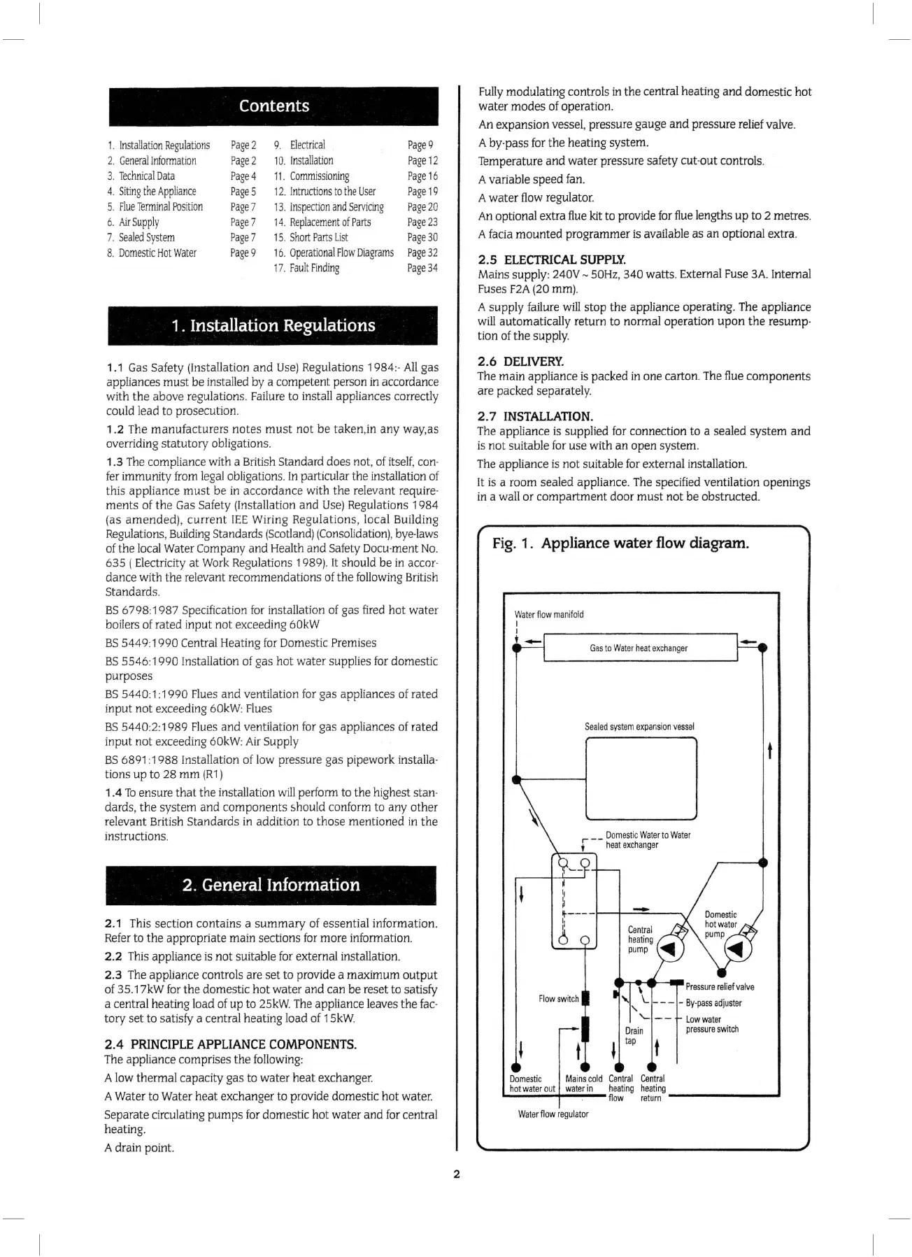
Fig.
1 . Appliance water flow
diagram.
Gas
to
Wa
t
er
heat
exchanger
S
ea
l
ed
sys
tem
ex
pa
r.sion
vess
el
Domestic W
at
er
to
Wa
t
er
r --
hea
t exch
ange
r
,>,
-
'---,
\
Pressure
re
li
ef
valve
'-
\._
- - - - B
y-pass
ad
j
us
ter
'
'-
--
Low
wa
t
er
press
ure
sw
itch
t
D
omest
ic M
ai
ns
cold Cen
tr
al
Central
ho
t water
out
water in h
eat
in
g
hea
t
ing
flow
r
eturn
-------.....1
W
ater
flow
regulator
 Loading...


