14. Replacement of Parts
14
.1.
WARNING.
Switch off
the
electricity
and
gas
supp
li
es before replacing
any
components.
After
the
replacement of any components, check for
gas
sound-
ness where relevant
and
carry
out
functi
ona
l checks
as
desc
ri
bed
in
Section
11
.
14.2.
COMPONENT ACCESS.
To
replace components it is necessary to remove one or more sec-
tions
of
the
cab
in
et
and
cover
plates
within
the
appliance
as
described
in
Section 13.3 together with
the
facia
and
control box
as
described in the
notes
fo
llo
wing.
(a)
Facia. Remove
the
inner cover
pane
l
as
described in Section
13.3
(b)
. Remove
the
three screws which hold the facia assem-
bly
in
position. Lower the fascia assembly. The assembly can
be unhooked from its supports.
Do
n
ot
allow
it
to hang unsup-
ported. See
Fig
. 20.
(b)
Control Box. Remove
the
inner cov
er
pane
l
as
described in
Section 13.3
(b)
. Unscrew
the
two fixing screws
at
each end of
the control box.
Pull
the
complete assembly forward and
lo
wer
if
necessary.
The
assembly can be unhooked from its support
s.
Do
not allow it to
hang
unsupported. See
Fig
. 22.
Important
: The
fo
llo
wing components are secured to
the
appli-
ance with clips. See
Figs.
37
,
38
and
39
.
12
: Expansion
Vessel
13: Central Heating Pump
14: Domestic Hot Water Pump
15:
Wa
ter to Water Heat Exchanger
27: Gas to Water Heat Exchanger
Important
:
Co
mprehensive gasket/ 0-ring packs are available for
the
gas
and water connections on
the
appliance. See Section 15.
When replacing
th
ese components
the
connections
must
be fully
entered so
that
the clips can
pa
ss
completely into t
he
locating
groove.
The
clips must
not
be forced into place.
Any
'0' ring which shows sign of damage
must
be replaced.
Th
e
'0
' rings
can
be
lubricated
wi
th
a suitable lubricant
(i.e
. silicon
based
grease
or
glycerin) which is
non-reactive
with
the
eth
y-
lene- propylene nit
ril
e '0 ' rings.
14.3.
DRAINING THE APPLIANCE
Check
th
at
the
electricity supply to
the
appliance is turned
off.
Before removing any compon
ent
holding
water
, it is impo
rt
ant
that
as
much
wa
ter
as
poss
ibl
e is removed from the appliance.
(a)
Appliance Central Heating Circuit
Turn
off
the
central heating
flow
and return valves
at
the
app
li
-
ance.
See Figs.
21
and
28. These
are
operated
us
ing
an
adjustable s
pa
nn
er
or
a screwdriver.
Fit
a
tube
to the drain tap
and
open
the
tap
about
one turn.
See
Fig
.
28
. Pre
ss
in
the
non-return
valve
test
button
on
the
central he
at
ing
pu
mp
(left hand) to remove more water. See
Fig
. 39. Close the drain tap when the flow has stopped.
Some
water
will
remain in the expansion vessel,
pumps
and
Gas to Water he
at
exch
anger
and
extra care
must
be
taken
when removing these components.
(b)
Appliance Hot Water Circuit
Turn off
the
mains
water
supply
va
lve
at
the appliance. See
Figs
. 21
and
28.
Thi
s is operated using a flat blade screwdriver.
Later versions of
th
e water flow regulator have a drain screw
which
must
be loosened to remove more water. See Fig.
41
.
A
quantity
of
water
will remain
in
th
e
Wa
ter to Water
heat
exchanger
and
extra care
mu
st
be
taken when removing this
component.
23
14
.
4.
COMPONENT REPLACEMENT.
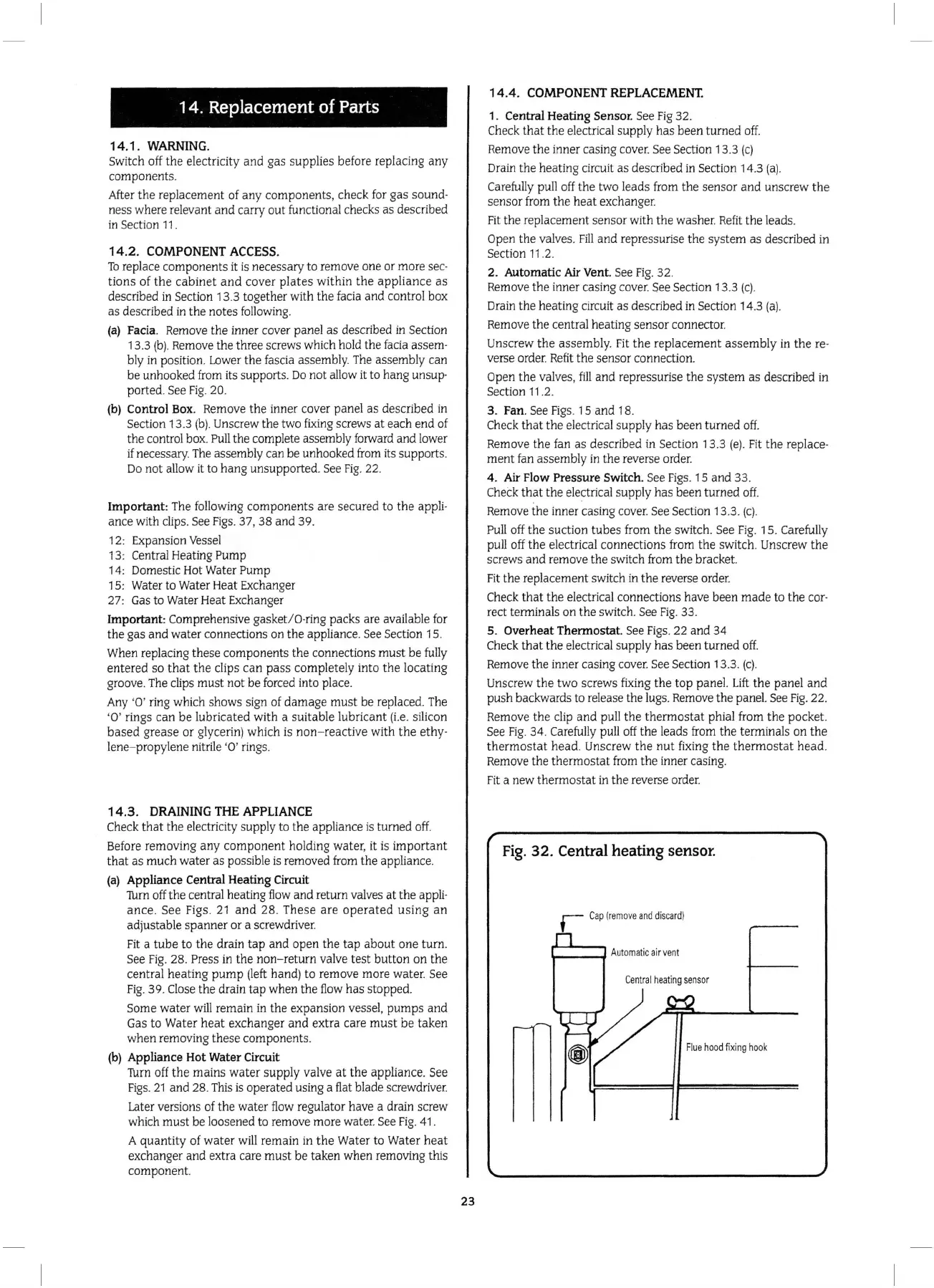
1. Central Heating Sensor. See
Fi
g
32
.
Ch
eck th
at
the
electrical supply has been turned off.
Rem
o
ve
the
inner casing cover. See Section 13.3
(c)
Drain
the
he
at
in
g circuit as described
in
Secti
on
14.3 (a
).
Ca
refu
ll
y pull
off
the
two leads from
the
sensor
and
unscrew
th
e
sensor from
th
e
heat
exchanger.
Fi
t the replacement sensor with the washer.
Refi
t
the
leads.
Open the
va
lves.
Fill
and
repressuri
se
the syst
em
as
described
in
Section
11
.2.
2. Automatic Air Vent.
See
Fig
. 32.
Remove
the
inner casing cover. See Section 13.3
(c)
.
Drain
the
heating circuit as described in Section 14.3 (a).
Remove
the
central
hea
ting sensor connector.
Unscrew
the
assembl
y.
Fit
the
repl
acement
as
sembl
y in
the
re-
verse order.
Re
fi
t the sensor connection.
Op
en
the
va
lves,
fill
and
re
pr
essuri
se
the
system
as
described
in
Section
11
.2.
3. Fan.
See Figs. 15
and
18.
Check
that
the
electrical supply has been turned off.
Remove
the
fan as describ
ed
in
Se
ct
i
on
13.3 (
e).
Fit
the
replace-
ment
fan
ass
embly
in
the reverse order.
4. Air Flow Pressure
Sw
it
ch
. See
Figs
. 15 and
33
.
Ch
eck
th
at
th
e electrical supply has been
tu
rned
off.
Rem
ove
the
inner cas
in
g cover. See Section 13.3. (
c)
.
Pull
off
the
suction tu
bes
from
the
switch.
Se
e
Fig
.
15
. Carefully
pull off
the
el
ectrical connections
fr
om
the
switch. Unscrew the
sc
rews
and
remove
the
switch from
the
bracket.
Fit the replacement switch in
the
reverse orde
r.
Check
that
the
electrical connections have been
made
to the
cor-
rect terminals on
the
switch. See
Fig
.
33
.
5. Overheat Thermostat. See Figs.
22
and
34
Ch
eck
that
the
electrical su
pp
ly has been turned off.
Rem
ove
the
inner casing cover. See Section 13.3.
(c).
Unscrew
the
two screws fixing
the
top panel.
Lift
the
panel
an
d
push
backwards to release the lugs. Remove the panel.
Se
e
Fig
.
22
.
Rem
ove
the
cl
ip and
pu
ll
the
thermostat
phial from the pocket.
See Fi
g.
34
. Carefully pull
off
the
leads from the terminals
on
th
e
thermostat
head
. Unscrew
the
nut
fixing
the
thermo
stat
head
.
Remove
the the
r
mostat
from
the
inner casing.
Fit
a new
thermostat
in
the reverse order.
Fig.
32. Central heating sensor.
Fl
ue
hood
fixi
ng
ho
ok
 Loading...


