8. Domestic Hot Water
8.1 The following are general requirements
and
,
if
necessary,
ref-
erence should be made to the local Water Company before fitting
the
appliance.
8.2
MAINS
COLD
WATER
INLET.
Devices
capa
ble of preventing
the
flow of expansion water
must
not
be
fitted unless separate arrangements have been
made
.
An
expansion vessel can be fitted within the casing of the appliance
if
necessary.
An
RC
,/2 connection is provided on the flow switch assembl
y.
See
Fig. 38. A Zilmet
Z160 is the preferred type. A thread sealant com·
patible with potable water
must
be
used. ·
The final
600
mm
of
the
mains cold water connection to the appli·
ance
sh
ould
be
made in copper tube only.
The appliance
is
suitable for a mains supply having a maximum
pressure of
up
to 10
bar
(145 lb
./i
n.
2
).
A pressure reducing valve
must
be
fitted,
if
necessary.
The appliance is fitted with
an
isolating valve.
The
pump
, which circulates water to the domestic
hot
water
heat
exchanger, is
set
at maximum
and
must
not
be
adjusted.
8.3
HOT
WATER
SUPPLY
AND
FLOW
REGULATION
.
The minimum supply pressure
for
the maxi
mum
flow of hot water
is 1.3
bar
(20 lb
./
in
.
2
).
The maximum
hot
water flow rate
is
12.5
litres
/min.
( ± 15%) (2.8 gall
on
s/
min.) giving a temperature rise
of nominally
41
°
C.
The temperature rise of the domestic
hot
water
is
maintained by
the
automatic modulation of
the
heat input to the boiler.
The
temperature
of
the
incoming
water
is
raised
by a fixed
amount.
In
winter, when
the
ma
ins inlet temperature is lower, the
water flow
at
the
taps
must
be
reduced to maintain the required
delivery temperatur
e.
Ifthere are long pipe runs to the taps or shower then it is suggest·
ed
they
be
insulated to prevent the rapid cooling of residual
hot
water in
the
pipes after the
tap
or shower
has
been turned
off.
8.4
TAPS
AND
VALVES
.
Hot
and
cold
tap
s
and
mixing valves u
sed
with this
app
li
ance
must
be
suitable
for
operating
at
a mains pressure of up to 10
bar
(150 l
b./in.
2
).
8.5
SHOWERS
(FIXED
HEAD
TYPE).
No
anti-syphonage arrangements are necessary. Thermostatically
controlled shower valves
will
give extra comfort
and
guard against
the
flow of water
at
too high a temperature.
8.6
SHOWERS
(LOOSE
OR
FLEXIBLE
HEAD
TYPE)
.
A loo
se
h
ead
shower hose
must
be
fixed so
that
the
head ca
nn
ot
fall
closer
than
25 mm
(1
in
.)
above the top edge of the bath to pre·
vent
its immersion in
bath
water. Alternatively
the
shower
must
incorporate
or
be
fitted with
an
anti·syphonage device
at
the point
of
the
flexible hose connections.
Thermostatically controlled shower valves
will
give extra comfort
and
guard
aga
inst
the
flow of water
at
too high a temperature.
8.7
BIDETS.
The supply of
hot
and
cold mains water direct to a bidet is per·
mitted (subject
to
local Water Company requirements) provided
that
the
bidet is of the over·rim flushing type. The outlet(s) should
be
shrouded a
nd
unable to have
any
temporary
hand
held spray
attached.
No
anti·syphonage arrangements are necessary.
8.8
USE
IN
HARD
WATER
AREAS
.
As
the
maximum
temperature
of
th
e
domesti
c
hot
wa
ter
heat
exchanger is limited by
the
electronic control circuit, there is
nor
·
mally
no
need for water treatment to prevent scale accumulation.
In
exceptional circumstances a
de
vice capable of preventing scale
formation
can
be
fitted.
9
Installation of a scale inhibit
or
assem
bly
should
be
str
ictly in
accordance with the requirements of the local Water
Compan
y.
An
isolating valve
to
facilitate servicing should be incorporated.
The wa
ter
hardnes
s
ma
y
be
determined
using a
st
andard
test
paper
or
by reference to the local Water Compan
y.
Further infor·
mation
ma
y
be
obta
ined from Worcester Heat Sy
stems
Ltd.
9. Electrical
See
Figs.
7, 8, 9a,
9b
and 10.
9.1
MAIN
S
SUPPLY
.
Supply: 240V -
50
Hz,
340 watts. External Fuse
3A.
In
ternal Fuses
F2A
(
20
mm). It
must
be possible
to
completely isol
ate
the appli·
ance.
Connection to
the
mains
supply
should
be
via a double pole
isolato
r
with
a
contact
sepa
ration
of
3mm
in all
poles
and
supplying the appliance and controls
only.
The
app
liance
must
be
earthed.
Mains Cable. 0.75
mm
2
(24 x
0.20
mm
) to
BS
65
00
Table 16.
Temperature rated
at
100
°C.
If
a new cable is needed it
mus
t
be
connected into the terminals
marked
L (Brown
or
Red lead), N (Blue
or
B
lack
lead)
and
~
(Green/
Yellow
or
Green lead)
and
be
held securely in
the
cable
clamp. When fixing the mains lead or external control leads check
that
suffici
ent
has
been left within the casing to allow
the
control
box to
be
brought forward
and
lowered.
9.2
MAINS
CONNECTION
.
To
gain access to
the
mains connection point
on
the main driver
board remove
th
e facia assembly.
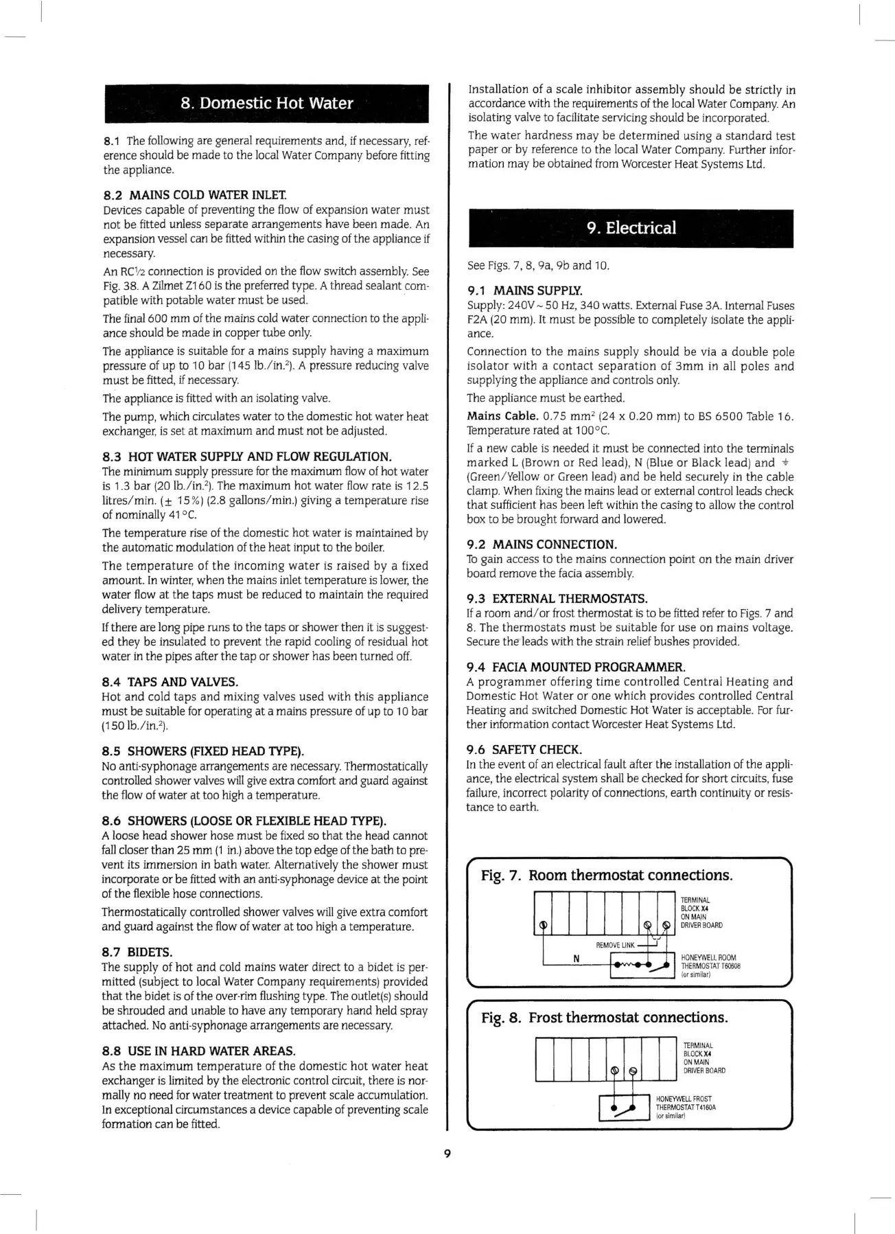
9.3
EXTERNAL
THERMOSTATS.
If
a room and/ or frost thermostat is to
be
fi
tted refer to
Figs
. 7 and
8. The
the
rm
ostats
must
be
suitable for use
on
mains
voltage.
Secure
t
he
leads with the strain relief bushes provided.
9.4
FACI
A
MOUNTED
PROGRAMMER.
A
programmer
offeri
ng
time
controlled
Cen
tral
Heatin
g
and
Domestic Hot Water
or
one
which provides c
ont
rolled Central
Heating
and
switched Domest
ic
Hot
Wa
t
er
is
acceptable.
For
fur·
ther
information contact Worcester Heat Syst
ems
Ltd.
9.6
SAFETY
CHECK.
In
the event of
an
electrical
fa
ult after the ins
ta
llation of
the
appli·
ance, the electrical system
sha
ll
be
checked
for
sho
rt
circuits, fuse
failure, incorrect polarity of connections, earth continuity or resis·
tan
ce to earth.
Fig.
7. Room thermostat connections.
(p
I
~
~
RE
M
OVE
LINK
-
.:/
N
I
•..,....-A
I
TERM
I
NA
L
BLOC
K
X4
ON
MA
IN
DR
I
VER
BOARD
HO
NEYWE
LL
ROO
M
TH
ERM
OSTATT60608
l
or
si
mil
a
r)
Fig
. 8. Frost thermostat connections.
TER
MI
NA
L
BLOCK
X4
ON
MAIN
~
~~
D
RIVER
BOARD
r
I
HONEYWELL
FROS
T
...........
THER
MOSTATT4
160A
(or
s
imilar)
 Loading...


