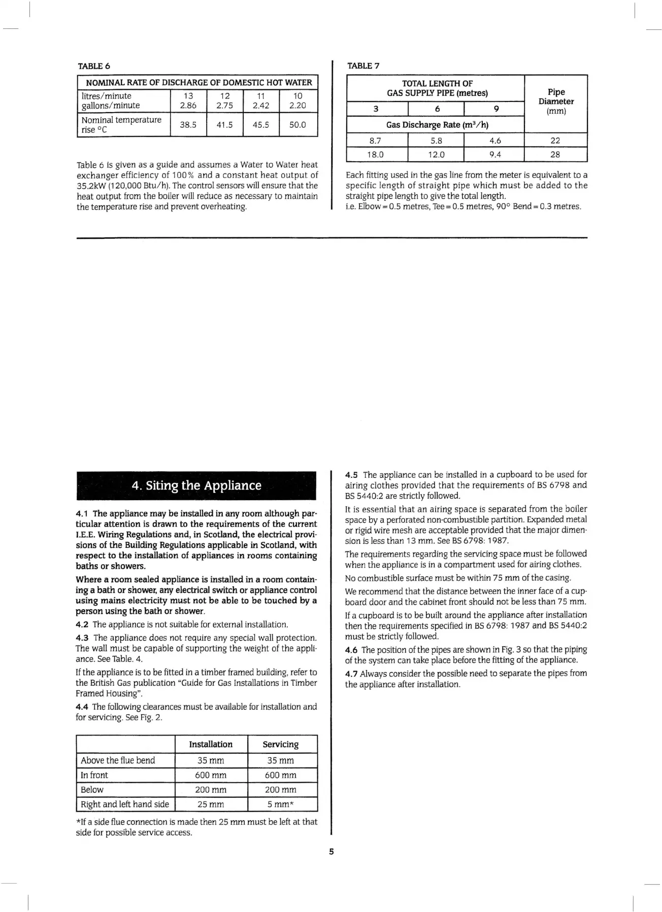
TABLE
6
NOMINAL
RATE
OF
DISCHARGE
OF
DOMESTIC
HOT
WATER
litre
s/
mi
nut
e
13 12
11
10
gallo
ns/
minute 2.86 2.75 2.42 2.
20
Nominal
te
m
pe
rature
38
.5 41.5 45.5
50
.0
ri
se
oc
T
ab
le 6
is
given
as
a guide
and
assumes
a Water to Water
heat
exch
an
ger
efficiency of 1
00
%
and
a
constan
t
heat
ou
t
put
of
35.2kW (120,0
00
Btu/
h)
. The control sensors wi
ll
ensure
tha
t
the
h
eat
ou
tp
ut
fro
m
the
boiler w
ill
reduce
as
necessary to maintain
the
te
mp
erature rise
and
prevent overheating.
4. Siting the Appliance
4.1
The
appliance
may
be installed
in
any room although
par
·
ticular attention is drawn
to
the requirements of the current
I.E.E.
Wiring
Regulations and, in Scotland, the electrical
provi
-
sions of the Building Regulations applicable
in
Scotland, with
respect
to
the installation of applianc
es
in rooms containing
baths
or
showers.
Where a room sealed appliance is
in
stalled
in
a room contain-
ing a bath
or
shower,
any electrical switch
or
appliance control
us
i
ng
mai
ns
electricity must not be able
to
be touched by a
person using the bath
or
shower.
4.2 The appliance
is
not suit
ab
le
fo
r external insta
ll
ation.
4.3 The a
pp
liance
do
es not require any special wa
ll
protection.
The
wa
ll
must
be
capable of supporting
th
e weight of
the
appli-
ance. See Table. 4.
If
the
appliance is to be fitted
in
a timber framed building, refer to
the British G
as
publication "Guide for Gas Insta
ll
ations
in
Timber
Framed
Housing
".
4
.4
The
followi
ng clearances
must
be
available
for
installation and
for servic
in
g. See
Fig.
2.
In
sta
llatio
n
Se
rv
icing
Above the flue
be
nd
35mm
35mm
In front
600mm 600mm
Below
200mm
2
00mm
Right
and
left hand side 25
mm
5mm
*
*
If
a side
fl
ue connection is m
ade
then 25
mm
mu
st
be
left at th
at
side for possible service access.
5
TABLE
7
TOTAL
LENGTH
OF
GAS
SUPPLY
PIPE
(metres)
Pipe
I I
Diameter
3 6 9
(mm)
Gas
Discharge
Rate
(m
3
/
h)
8.7
I
5.8
I
4.6
22
18.0
I
12.0
I
9.4
28
Each
fi
tting used in the gas line from t
he
me
ter
is equivalent to a
specif
ic
length
of
straigh
t p
ipe
which
must
be
added
to
the
stra
ig
ht
pipe length to give
th
e total length.
i.e.
Elbow= 0.5 metres, Tee= 0.5
me
tres,
90
°
Bend=
0.3 metres.
4.5
T
he
appliance can be installed in a cupboard to be used
for
airing
clothes
provid
ed
that
the
requireme
nts
of
BS
67
98
and
BS 5440
:2
are stri
ct
ly
follo
wed.
It is
essent
ial
that
an
airing
space
is
separated
from
the
boiler
space by a perforated non-combustible
part
ition. Expanded me
ta
l
or r
igi
d wire mesh are acceptable provided
that
the
ma
jor dimen-
sion is less than 13
mm
. See
BS
6798
:
198
7.
The requirements regarding
the
servicing space
mu
st
be followed
when
the
appliance is in a comp
artment
used for airing
cl
othes.
No
combustible surface m
us
t
be
within 7 5
mm
of
the
casing.
We rec
ommend
that
the distance between
the
inner face of a cup-
board do
or
and
th
e cabinet front should
not
be
Jess
than
75
mm
.
If
a cupboard is to
be
bu
ilt
around
the
appliance after installation
then
the requirem
ents
specified in
BS
6 798:
1987
and
BS
5440
:2
mu
st
be
strictly
fo
ll
owed.
4.6
The
position of
the
pipes are shown in
Fig
. 3 so
that
the
piping
of
the
system can take place before
the
fitting of
the
appliance.
4. 7 Always consider the po
ss
ible need
to
separate
th
e pi
pes
fr
om
the
appliance after installation.
 Loading...


