5. Flue Terminal Position
See
Fig
. 4.
5.1 The flue m
ust
be installed
as
specifi
ed
by
BS
5440
: Part 1.
5.2
T
he
standard
fl
ue l
ength
is
100
mm
(4
in.)
up
to
1000
mm
(39.3 in.). The
extended
flue length is 1001 mm (39.4 in.)
up
to
20
00
mm
(78.7 in.
).
5.3 The air
du
ct should
be
supported
at
the
joint of
the
extended
duct
and
the
brackets rigidly fixed to
the
wall.
5.4
The
termina
l
must
be
positioned
so
as
not
to
cause
an
obstruction
and
so
that
the
combustion products do
not
cause a
nuisance.
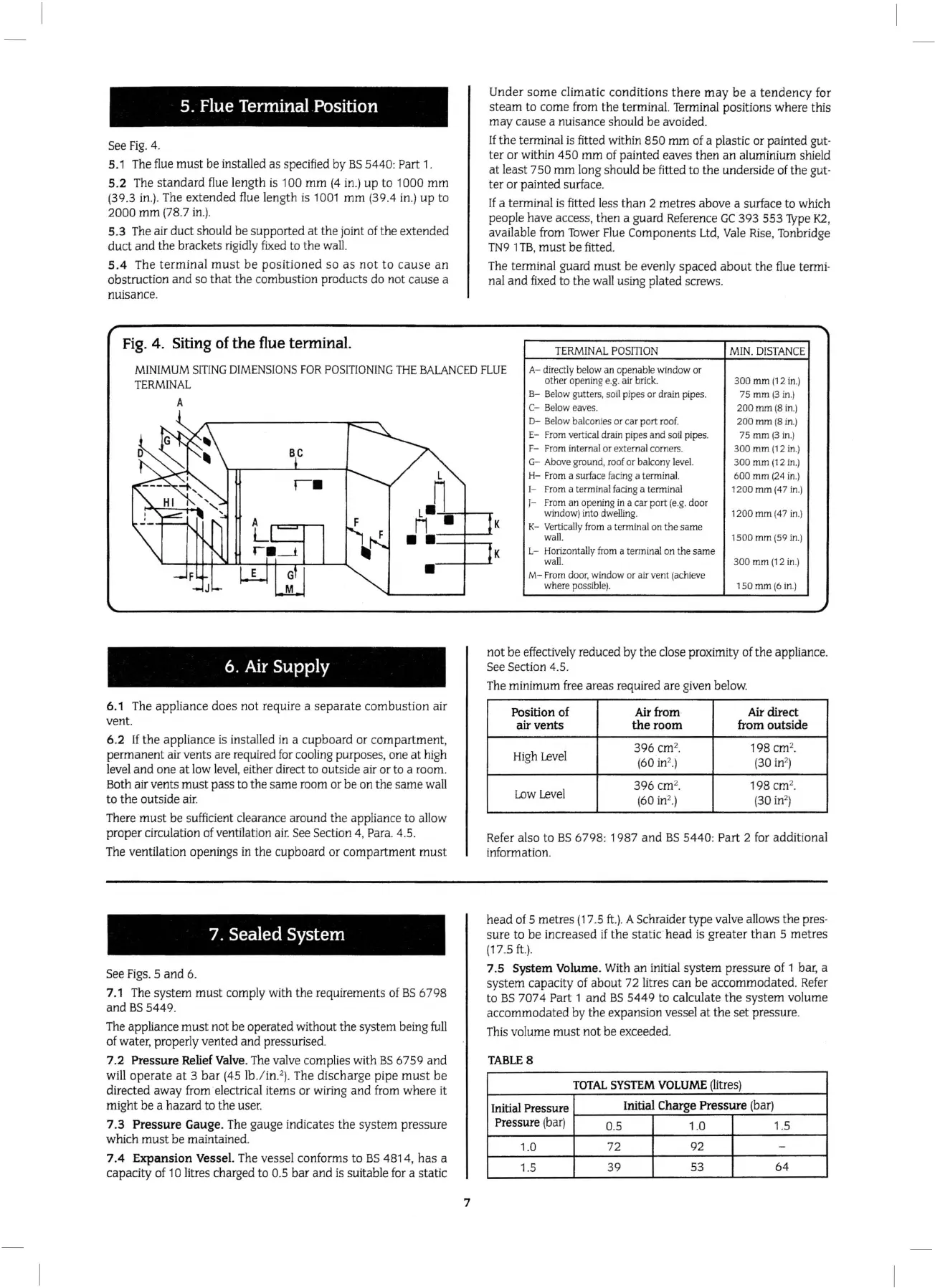
Fig.
4.
Siting of
the
flue terminal.
Under
some
climatic
conditions
th
ere
may
be
a t
endency
for
steam
to
come
from
the
terminal. Terminal positio
ns
where this
ma
y
cause
a nuisance should
be
avoided.
If
the
terminal is fitted within 850
mm
of a plastic
or
painted gut-
ter
or within
450
mm
of painted eaves
then
an
alumini
um
shield
at
least 7 50
mm
long should be fitted
to
the
undersi
de
of
the
gut-
ter
or pai
nt
ed surface.
If
a terminal is fitted less
than
2 metres above a surface to which
people have access,
the
n a guard Reference
GC
393
553
Type
K2
,
available from Tower Flue Components Ltd,
Va
le Rise, Tonbridge
TN9
1TB,
must
be
fitted.
The term
in
al guard
mu
st
be
evenly
spaced
about
the
flue termi-
nal
and
fixed
to
the
wa
ll
using plated screws.
TERMIN
AL
P
OSITI
ON
MI
N.
DI
ST
ANCE
MINIMUM
S!TING
DIMENS
I
ONS
FOR
P
OSITIONING
THE
BALANCED
FLUE
TERMINAL
A- directly bel
ow
an openable
wind
ow
or
other opening e.
g.
air
brick.
300
mm (1 2
in
.)
A
6.
Air
Supply
6.1 The appliance
does
not
require a
sepa
r
ate
combu
st
ion air
vent
.
6.2
If
the
app
li
ance is
in
stalled
in
a cupboard or co
mpartment,
permanent
air vents are required
fo
r coo
li
ng purposes, one
at
high
level
and
one
at
low level, either direct to outside air
or
to
a room.
B
ot
h air ve
nts
must
pass to
the
same
room
or
be
on the same wall
to
the
outside air.
There
must
be
sufficient clearance around
the
appliance to allow
proper
circulation of ventilation air. See Section 4, Para. 4.
5.
The ventilation openings
in
the
cupboard
or
co
mp
art
ment
mu
st
7. Sealed System
See Figs. 5
and
6.
7.1 T
he
system
must
comply with
th
e requirements of
BS
6
798
and BS 5
449
.
The appliance
must
not
be operated without
the
sys
tem
being
full
of
wa
ter, properly vented
and
pressuri
se
d.
7.2 Pr
ess
ur
e Relief Valve. The valve complies with
BS
6759 and
will
operate
at
3
bar
(45 lb
./
in
2
).
The di
sc
har
ge pipe
must
be
directed away from electrical items or wiring a
nd
from where it
might
be
a hazard to
th
e
us
e
r.
7.3
Pressure
Gauge. The
gauge
indicates
the
system
pressure
which
must
be maintained.
7.4 E
xpansion
Vessel. The vessel conforms
to
BS
48
14,
has
a
capacity of
10 litres charged
to
0.5
bar
and
is suitable for a static
7
B-
Below g
ut
ters, soil pipes
or
drain pipes.
75
mm(3
in
.)
C-
Be
l
ow
eaves.
200
mm
(8 in.)
0-
Bel
ow
balconies or car
port
roof.
200
mm
(8
in.)
E- From vertical drain pipes and soil pipes.
75
mm
(3
in.)
F-
From
intern
al
or
external comers.
300
mm
(12
in
.)
G-
Above ground,
roof
or
ba
l
cony
level.
300
mm
(1 2
in
.)
H-
From a surface facing a te
rmi
nal.
600
mm
(24 in.)
1-
Fr
om
a terminal fadng a terminal
1200
mm
(47 in.)
J-
From an opening in a car
port
(e.g.
door
wi
ndow
)
in
to dwelling.
1200
mm (47
in
.)
K- Vertically from a terminal
on
the same
wall.
1500
mm
(59
in
.)
L- Horizontally from a terminal on
the
same
wall.
300
mm (12
in
.)
M- From
door
.
window
or
air
vent (achieve
where possible). 1
so
mm
(6
in
.)
not
be
effectively reduced
by
the
close proximi
ty
of the appliance.
See Section 4.5.
The minim
um
free ar
eas
required are given below.
Position of
Ai
r from
Air
dir
ect
air
vents
the
room
from
ou
ts
ide
High
Level
396
cm
2
•
198 cm
2
•
(6
0in
2
)
(30
in
2
)
Low
Level
396
cm
2
.
198 cm
2
•
(6
0 in
2
.)
(
30
in
2
)
Refer also
to
BS
6798
: 1987
and
BS
5440: Part 2 for
addit
ional
inf
ormat
ion.
head
of 5 metres (17 .5
ft
.).
A Schraider
type
valve allo
ws
the
pres-
sure
to
be
increa
sed
if
the
static
head
is
grea
t
er
th
an
5 metres
(17.5
ft
.).
7.5
S
ys
tem
Vol
ume
. With
an
initial
system
pressure of 1 bar, a
sys
tem capacity of about 72 litres can
be
acc
omm
od
ated
. Refer
to
BS
7
07
4 Part 1 a
nd
BS
544
9
to
calcula
te
the
system
volume
accom
modated
by
the
expa
ns
ion vessel
at
the
se
t pressure.
This vol
ume
must
not
be
exceeded.
T
AB
L
ES
TO
TAL
SYSTE
M
VOLUM
E (litres)
Initial Press
ure
Initial Ch
arge
Pressure
(bar)
Press
ur
e
(bar)
0.5 1.0
1.5
1.0
72
92 -
1.5
39
53
64
 Loading...


