7.6 System Design Pressure. The maximum system design pres·
sure is 1.5
bar
(21.5lb
/in.
2
).
If
the
pressure is greater
than
2.6
bar
when
operating
at
maxi·
mum
system temperature, then
an
extra expansion vessel
must
be fitted
as
close as possible to
the
central heating return connec·
tion.
If
the
expansion
vessel
within
the
appliance
fails
it
must
be
replaced with
the
designated
spare
part. See Section 14.4
and
Se
ction 15.
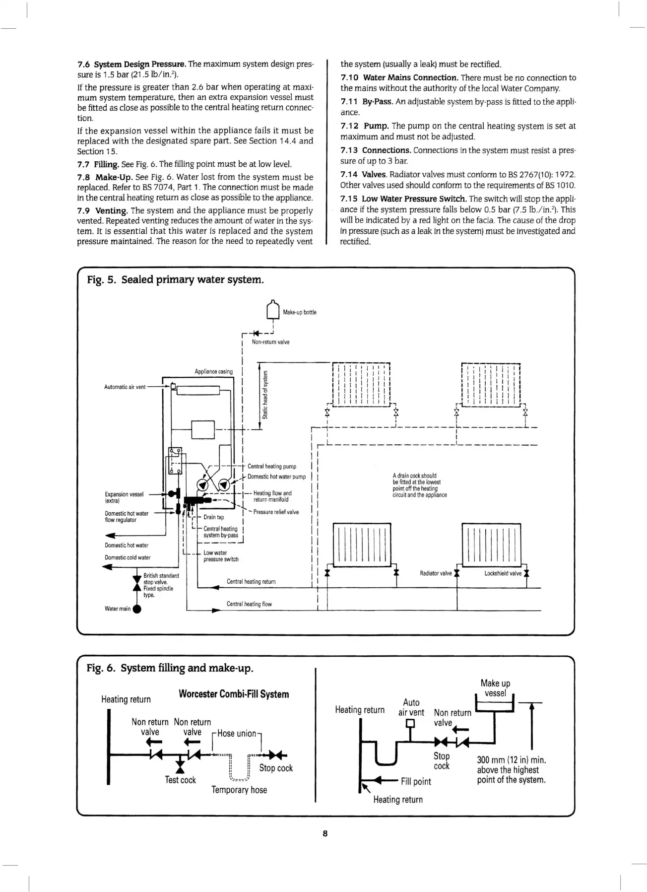
7. 7 Filling. See
Fig
. 6. The
filling
point
must
be
at
low level.
7.8
Make· Up. See
Fig
. 6. Water lost from
the
system
must
be
replaced.
Refer
to
BS
7074, Part 1.
The
connection
must
be made
in
the
central heating return as close as possible to the appliance.
7.9
Venting. The
system
and
the
appliance
must
be
properly
vented. Repeated venting reduces the amount of water in the
sys·
tern. It is essential
that
this
water
is
replaced
and
the
system
pressure maintained. The reason f
or
the need to repeatedly vent
Fig.
5. Sealed primary water system.
0
Ma
ke-up
bott
le
I
r-44----.J
1
No
n-
return
va
l
ve
l
Appliance
casing
I
I
I
I
I
E
Ex
pansion
ves
se
l
(extr
a}
Do
m
estic
ho
t
water
flow
regu
lato
r
Domest
ic
hot
wate
r
D
omestic
co
ld
wate
r
Br
itish
standard
stop
valve
.
F
ixed
spi
n
dle
type.
Low
wa
te
r
pressure
sw
i
tch
I
I
i
Central
h
eating
return
Ce
n
tra
l
heat
i
ng
flo
w
Fig.
6. System filling
and
make-up.
Heating
return
Worcester
Combi
-
Fill
System
Non
return
Non
return
valve
valv
e
+- +-
~Hose
unionl
.,.
___
"""'·-'P'V4
...
- -===
=u
;r:
: • t
~
4
ll ll
Stop
cock
11
II
'~'.:===
·.:'
'
'
Test
cock
Temporary
hose
8
the
system (usually a leak)
must
be
rectified.
7
.1
0 Water Mains Connection. There must
be
no connection to
the
mains without
the
authority of the local Water Company.
7.11
By
-Pass.
An
adjustable system by·pass is fitted to
the
appli·
ance.
7.12
Pump
. The
pump
on the central heating sy
stem
is
set
at
maximum
and
must
not be adjusted.
7. 1 3 Connections.
Connections in the system
must
resist a pres·
sure of
up
to 3 bar.
7.14
Valves. Radiator valves
must
conform to
BS
2767(10): 1972.
Other valves used should conform to
the
requirements of
BS
1010.
7.15 L
ow
Water Pressure Switch. The switch
will
stop the appli·
ance
if
the
system pressure falls below 0.5 bar (7.5 lb
./
in.
2
).
Th
is
will
be indicated by a red light on the facia.
The
cause of
the
drop
in pressure (such as a leak
in
the system) must be investigated and
rectified.
Heat
ing
return
A
drain
cock
shou
ld
be
fitted
at
the
l
owest
point
off
t
he
heat
i
ng
ci
r
cui
t
and
the
ap
p
lian
ce
R
adiato
r
va
l
ve
Auto
air
vent
..
, .....
1--
Fill
po
int
Heating
return
300
mm
(
12
in)
min.
above
the
highes
t
point
of
the
s
ys
tem
.
 Loading...


