1 7. Fault Finding
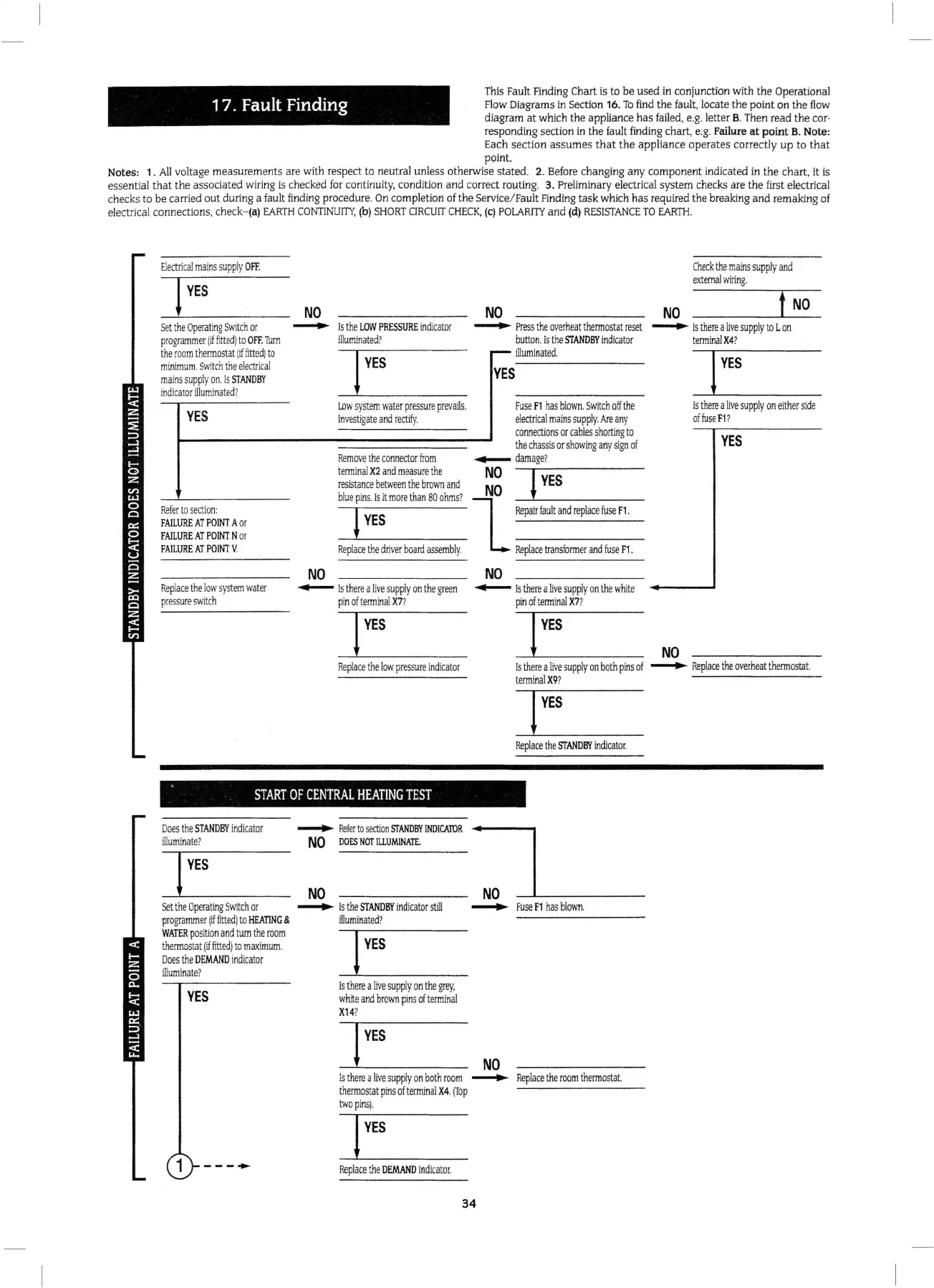
Th
is
Fau
lt
Find
i
ng
Chart
is
to
be used
in
conjunction with the Operational
Flow
Diagrams
in
Section
16
.
To
find
the
fault,
locate the point
on
the
flow
diagram at which the appliance has
fa
il
ed, e.g. letter B.
Then
read the cor·
responding section
in
the fa
ul
t
finding
chart, e.g. Failure at point B.
No
te:
Each
sec
ti
on
assumes
that
the appliance operates correc
tl
y up to that
point.
No
tes: 1.
All
voltage measurements are with respect to neutral unless otherwise state
d.
2.
Before
changing any component indicated
in
the
ch
art, it
is
essential that the associated w
iring
is checked
for
continui
ty,
condition and correct
ro
u
ting.
3.
Prelim
inary electrical system checks are the
first
elect
ri
ca
l
c
he
cks to
be
carried out during a fault
find
i
ng
procedure.
On
completion
of
the
Service
/
Fau
lt Finding task which has required the breaking and remaking
of
el
ec
tri
ca
l connections,
ch
eck-(a)
EA
RTH
CONTINUITY
,
(b)
SHORT
C
IRCUIT
CHEC
K,
(c)
POLARITY
and
(d
)
RES
I
STANCE
TO
EARTH.
Electrical
mains
supp
ly
OFF
.
Se
t the
Ope
ra
ti
ng
Swi
t
ch
or
pr
o
gram
mer
(if
fitte
d)
to
O
FF.
Tum
the
room
t
hermos
tat
(if
fi
tt
ed) to
m
inimum
Switch
the
electrical
mains
supply
on.
Is
STAND
BY
indic
a
tor
ill
uminated
?
YES
Ref
er
to
section:
FAILURE
AT
PO
INT
A
or
F
AIL
URE
AT P
OINT
N
or
FAILURE
AT
POI
NT
V.
Re
pla
ce
the
low
system
water
press
ur
e
switch
NO
NO
NO
Ch
e
ck
th
e
mains
su
pply
and
ext
ern
al
wiri
n
g.
.......,..
Is
the
L
OW
PRESSURE
in
dicato
r
illum
ina
te
d?
.......,..
Pres
s t
he
ov
erhea
t t
hermosta
t
reset
.......,..
Is
there
a
liv
e su
pply
to
Lon
button
. Is the
STANDBY
indi
cat
or
t
erminal
X4
?
NO
YES
YES
illuminated
.
-,~
-
------
Lo
w
system
wate
r p
ressure
prevails.
In
vestigate
and
rectify
.
Fuse
F1
has
bl
own
. S
witch
o
ff
the
el
ectri
cal
ma
in
s
su
pp
ly.
Ar
e
an
y
c
onne
ct
ions
or
c
able
s sho
rtin
g to
the c
hassis
or s
how
in
g
an
y
sign
of
Remove
th
e
co
nn
ector
fro
m
~
dam
age?
te
rm
inal
X2 and mea
su
re
the
NO
-
..-l-------
NO
YES
res
ista
n
ce
be
twe
en
the b
ro
wn
and
bl
ue
pin
s.
ls
it
mor
e
than
80
ohms?
l
-
--'-T____
_
__
_
Repair
fault
and
replac
e
fus
e
F1.
+YES
Re
pl
ace
the
dri
v
er
boa
rd
ass
embl
y.
Replace
tr
ans
fo
rm
er
and
fus
e
F1
.
NO
Is t
her
e a
live
su
pp
ly
on
eit
h
er
si
de
of
fu
se
F1?
YES
~
Is
t
he
re a
li
ve
su
pp
ly
on
the
gr
een
pin
of t
erminal
X7?
~
Is
there
a
live
suppl
y on
th
e
wh
ite
pin
of
termin
al
X7
?
Re
pla
ce
the
l
ow
pr
essur
e
indic
a
tor
NO
Is
th
e
re
a
liv
e s
uppl
y
on
b
oth
pi
ns
of
.......,..
R
eplace
th
e over
heat
the
rm
o
sta
t
t
erminal
X9
?
I
YES
Replace
the
ST
ANDBY
indicato
r.
START
OF
CENTRAL
HEATING
TEST
Does
t
he
S
TANDBY
indicator
illumi
nat
e?
Se
t
the
Ope
r
atin
g S
wi
t
ch
or
progr
a
mme
r
(rr
fitted)
to
HEATING
&
W
ATE
R p
ositio
n
and
turn
th
e
room
t
herm
ostat
(if
fitted)
to
m
aximu
m.
Does
th
e
DEMAND
in
dic
a
tor
ill
um
inat
e?
YES
1
----
.......,..
R
efer
to
section
SfAND
BY
IND!CA1UR
NO
DO
ES
NOT
ILLU
M
IN
ATE
.
NO
.......,..
Is
the
ST
ANDBY
in
di
cator
stil
l
illumina
te
d?
Is
th
ere
a
live
supp
ly
on
the
grey,
white
an
d
bro
wn
pins of
terminal
X14
?
•
NO
.......,..
Fuse
F1
h
as
blown.
NO
Is t
he
re a
li
ve s
upp
ly
on
b
oth
room
.......,..
Rep
l
ace
the
room
thermost
at
therm
osta
t p
ins
of
t
ermin
al
X4
.
[fop
tw
o pi
ns
).
Repl
ac
e
th
e
DEMAND
i
nd
icator.
34
 Loading...


