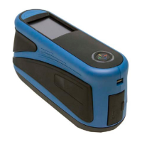
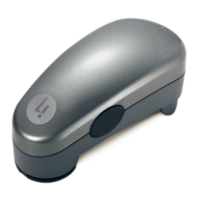
RapidMatch
TM
GO Spectrophotometer
8
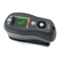
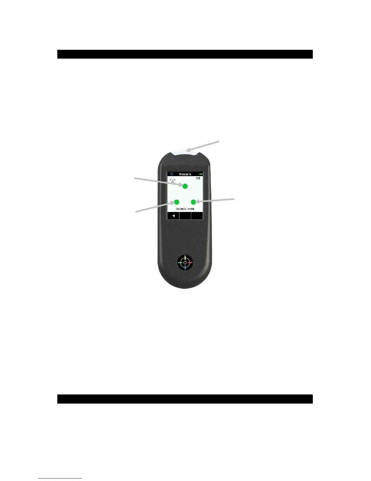
6. Contact Sensors, Indicators and LEDs
The indicators in the screen are arranged in the same pattern as the contact
sensors located around the measurement port.
• Green Indicator: ideal contact is being applied to the corresponding
sensor. A measurement can be taken when all three indicators illuminate
green.
• Red Indicator: the required contact is not being applied to the
corresponding sensor. Correct contact must be applied to achieve a
green indicator condition.
The multi-color LED located on the front of instrument provides visual
feedback on the status of a measurement and contact sensors.
• Green LED: Indicates all three contact sensors are activated properly
and a measurement can now be triggered.
• Red LED: Indicates one or more of the contact sensors is not properly
activated or an error has occurred during a measurement.
• Blue Pulsing LED: Indicates the instrument is in standby mode with the
USB cable plugged into the computer and charging.
• Off: Indicates the instrument is off and not ready to measure.
7. Home Screen
When the instrument is powered-up, the home (top level) screen appears
after the startup procedure is complete. Select the modes by tapping the
icons located on the display screen.
 Loading...