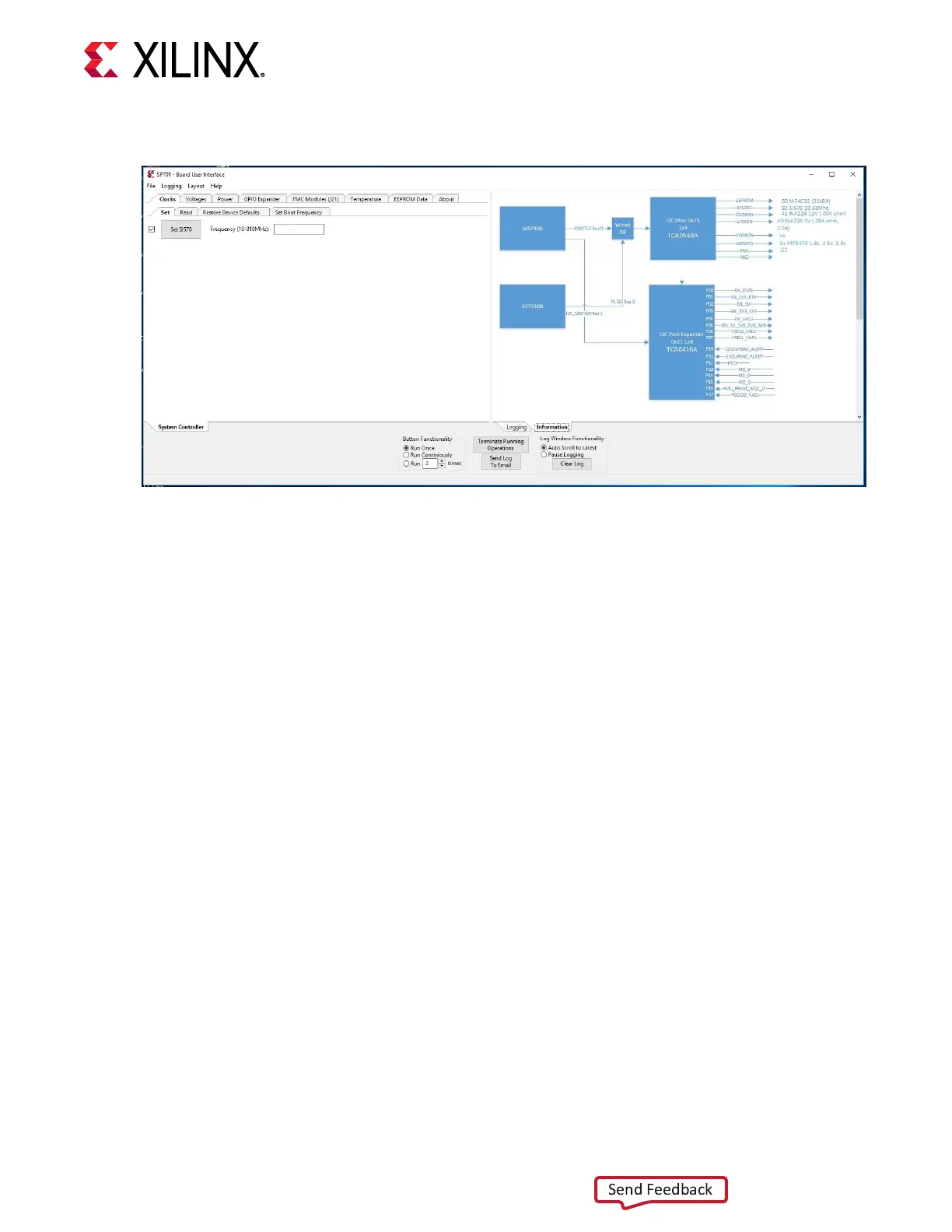
Figure 19: SCUI Graphical User Interface
On the rst use of the SCUI, go to the FMC → Set VADJ → Boot-up tab and click USE FMC
EEPROM Voltage. The SCUI buons are grayed out during command execuon and return to
their original appearance when ready to accept a new command. See the SP701 System
Controller Tutorial (XTP551) and the SP701 Soware Install and Board Setup Tutorial (XTP552)
for more informaon on installing and using the System Controller ulity.
For more details, see the MSP430F5342 data sheet on the Texas Instruments website. The
detailed FPGA connecons for the feature described in this secon are documented in the
SP701 board XDC le, referenced in Appendix B: Xilinx Design Constraints.
FPGA Mezzanine Card Interface
[Figure 2, callout 7]
The SP701 evaluaon board supports the VITA 57.1 FPGA mezzanine card (FMC) specicaon
by providing a low pin count (LPC) FMC connector at J21. LPC connectors use a 10 x 40 form
factor that is parally populated with 160 pins. The connector is keyed so that a mezzanine card,
when installed in the FMC LPC connector on the SP701 evaluaon board, faces away from the
board. The FMC LPC connector pinout is shown in the Appendix A: VITA 57.1 FMC Connector
Pinouts.
FMC LPC Connector J21
[Figure 2, callout 7]
The 160-pin connector J21 implements paral FMC LPC connecvity (refer to schemac
0381874 and the XDC le for details).
Chapter 3: Board Component Descriptions
UG1319 (v1.0) July 12, 2019 www.xilinx.com
SP701 Board User Guide 36

 Loading...


