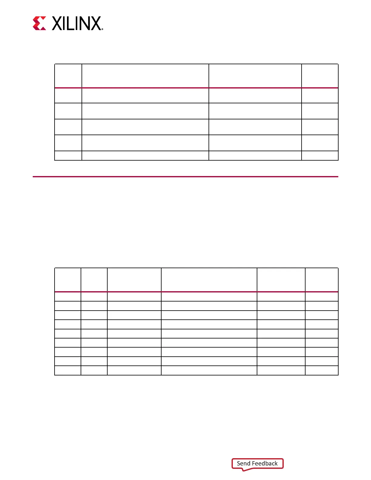
Table 3: Board Component Locations (cont'd)
Callout Feature [#] = Bottom Notes
Schematic
Page
Number
26 Configuration options, FPGA U1 configuration mode
4-pole DIP switch, (SW13)
Wurth 416131160804 3
27 XADC/SYSMON 2x10 shrouded/keyed
Header (J24)
Samtec TST-110-01-G-D 22
28 Encryption Key Battery Backup Circuit
Battery retainer [B1]
Keystone 2998 3
29 System Controller MSP430 2x7 0.1"
JTAG Header (J22)
Tyco 5103308-2 19
30 Ethernet 1x4 0.1" JTAG header (J10) Sullins PBC36DAAN 9
Default Switch and Jumper Settings
Jumpers
Default jumper sengs are listed in the following table. The table also references the respecve
schemac (0381874) page numbers.
Table 4: Default Jumper Settings
Callout Jumper Type Function Default
Schematic
Page
Number
31 J38 2-pin male header USB JTAG enable Jumper ON 5
32 J2 2-pin male header FPGA U1 CFGBVS_0 Jumper OFF 3
33 J6 2-pin male header FT4232 U6 SUSPEND Jumper OFF 5
34 J23 3-pin male header FPGA U1 XADC_VCC Select 2-3 22
34 J25 3-pin male header REF3012 U29 V
in
Select 1-2 22
34 J26 3-pin male header FPGA U1 XADC_VREFP Select 1-2 22
34 J27 2-pin male header GND-to-J28/L12 Jumper ON 22
34 J28 2-pin male header J28/L12-to-XADC_GND Jumper OFF 22
35 J35 2-pin male header Power System Inhibit Jumper OFF 23
Switches
Default switch sengs are listed in the following table. The table also references the respecve
schemac (0381874) page numbers.
Chapter 2: Board Setup and Configuration
UG1319 (v1.0) July 12, 2019 www.xilinx.com
SP701 Board User Guide 12

 Loading...


