Virtex-5 LXT/SXT/FXT FPGA Prototype Platform www.xilinx.com 13
UG229 (v3.0.1) May 21, 2008
Detailed Description
R
Detailed Description
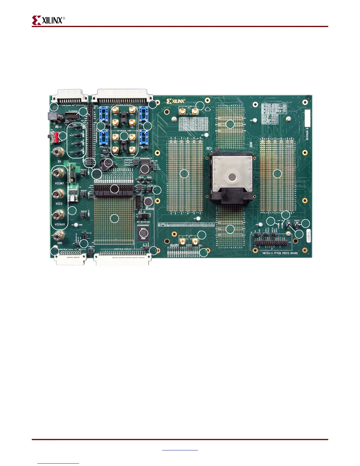
The Virtex-5 LXT/SXT/FXT FPGA prototype platform board is shown in Figure 2. The
numbered sections on the pages following the figures contain details on each feature.
Note:
The image might not reflect the current revision of the board.
1. Power Switch
The board has an onboard power supply and an ON|OFF power switch (SW3). The green
LED (DS19) lights up to indicate power from the power brick connector or the 5V jack (J32).
On Position
In the ON position, the power switch enables delivery of all power to the board by way of
voltage regulators situated on the backside of the board. These regulators feed off a 5V
external power brick or the 5V power supply jack (J32).
The voltage regulators deliver fixed voltages. The maximum current range for each supply
varies. Table 1, page 14 shows the maximum voltage and maximum current for each
onboard power supply. If the current exceeds maximum ratings, use the power jacks to
supply power to the DUT.
X-Ref Target - Figure 2
Figure 2: Detailed Description of Virtex-5 LXT/SXT/FXT FPGA Prototype Platform Components
UG229_02_022008
1
9
3
19
4
20
21
10
11
2
8
7
5
6d
6b
10
6a
6c
22
13
13
13
12
13
15
16
18
17
22
14
23
 Loading...
