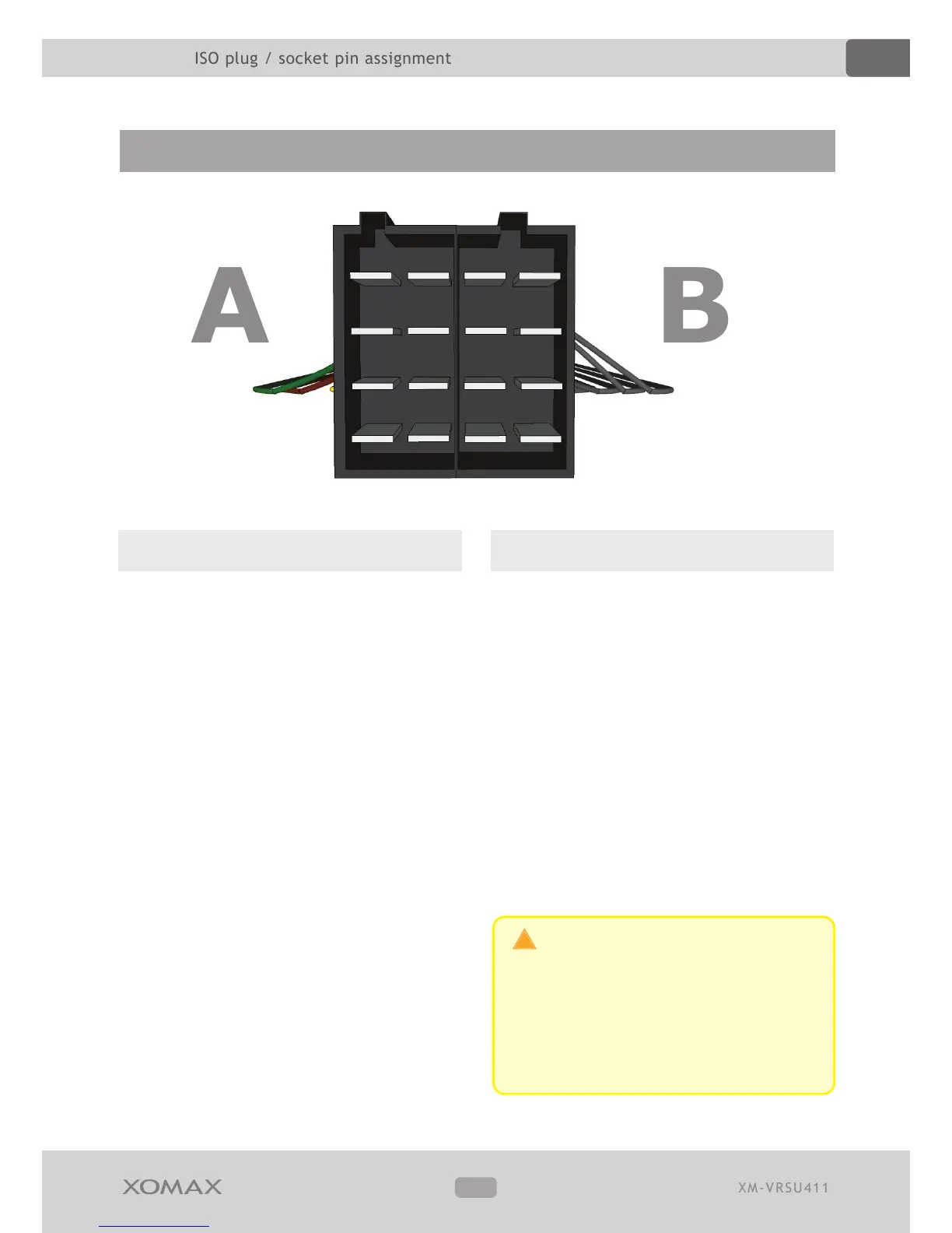
ISO plug / socket pin assignment
Port A (power supply)
On the A side you can nd the port for
power supply.
A1 – spare
A2 – spare
A3 – spare
A4 - (+) 12Volt battery / steady plus *
A5 – electric antenna (+)
A6 – spare
A7 - (+) 12Volt ignition plus *
A8 – minus / ground (-)
* Some vehicle manufacturers use their
own pin assignment. Especially the
terminals A7 (ignition plus) and A4 (steady
plus) are often interchanged. The incorrect
connection in this case leads to following
problem: the unit can not be turned on if
the ignition is o and all the saved settings
are lost as soon as the unit will be turned
o. If these problems appear the connec-
tions A4 and A7 should be interchanged.
ISO plug / socket pin assignment
Though the design of ISO port is
standardized, it's pin assigment is not
and may vary. Thus in case of mismatch
of connections due to dierent pin assig-
nments a simple plug'n'play connection
may lead to grievous errors.
2 1 2 1
4 3 4 3
6 5 6 5
8 7 8 7
Port B (loud speakers)
On the B side you can nd the speakers
terminals.
B1 – rear speaker right (+)
B2 – rear speaker right (-)
B3 – front speaker right (+)
B4 – front speaker right (-)
B5 – front speaker left (+)
B6 – front speaker left (-)
B7 – rear speaker left (+)
B8 – rear speaker left (-)
The terminals are colored by pairs, in each
case one (+) and one (-).
 Loading...