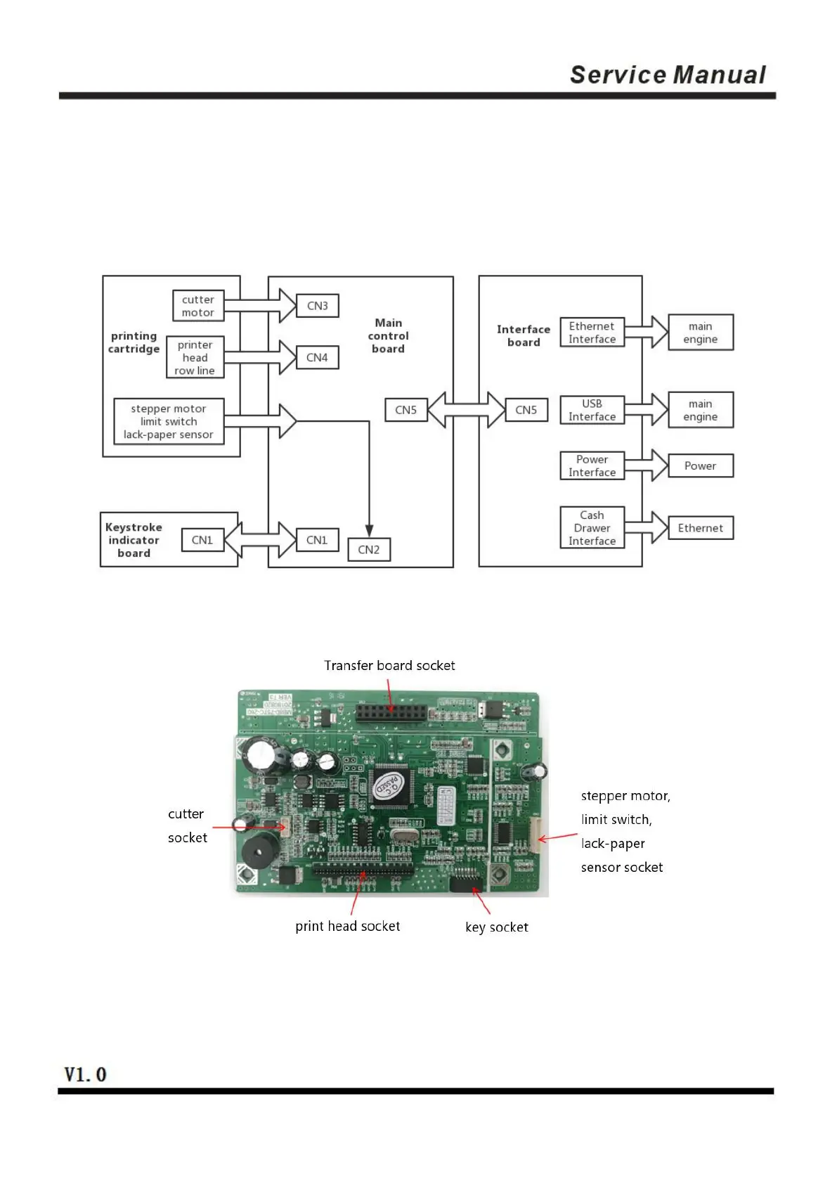
2.2 Connecting Diagram for Components of the Control Panel
The printer composed of main control board, printing cartridge, cutter, keys and buttons is connected to the
mainboard via connectors or pinboard, and the following is the connecting diagram of USB+network
interface and USB+serial interface control panel assembly:
Fig 2.2.1 Connection Diagram of USB+ Network Interface Control Panel
Fig 2.2.2 Position Diagram for USB+ Network Interface Control Panel
 Loading...