4.2 Test function: .......................................................................................................... 18
4.3 Read ECU: ............................................................................................................. 21
4.4 Read DTCs: ............................................................................................................ 22
4.5 Clear DTCs: ........................................................................................................... 23
4.6 Read live Data: .......................................................................................................... 24
4.7 Special function: ..................................................................................................... 25
4.8 Actuating components test: .................................................................................... 25
5. Setting: ................................................................................................................................ 26
6. Diagnose report ................................................................................................................... 30
6.1 Diagnose report: ........................................................................................................ 30
6.2 Data playback ............................................................................................................ 31
7. One-click upgrade: .............................................................................................................. 31
8. Xtool Cloud System ............................................................................................................ 32
9. Remote control: ................................................................................................................... 33
Chapter III Location of Diagnostic link connectors on Different vehicle Models .......................... 35
1. Diagnostic link connectors locations of various vehicle models: ....................................... 35
2. Location diagram of vehicle diagnostic link connectors: .................................................... 39
3. Diagnostic Link Connectors Terminal Definition and Communication Protocols .............. 40
Chapter IV Additional Information ................................................................................................. 43
1. Description of OBDII and the function of sensor components ........................................... 43
1.1 OBDII function description ....................................................................................... 43
1.2 Sensor element function ............................................................................................ 45
2. Common faults and elimination of electronic control system ............................................. 51
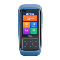
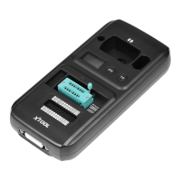
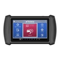
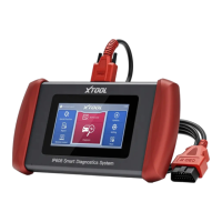
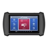
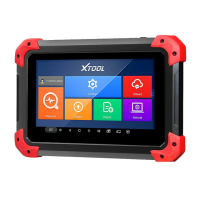
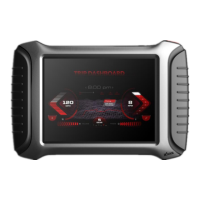
ChapterI About A80 BT
1. Appearance
 Loading...