VESDA by Xtralis
VESDA VFT Product Guide
www.xtralis.com 11
3 Installation
The detector shall be installed in accordance with the following installation instructions and in a manner
acceptable to the local Authority Having Jurisdiction (AHJ). The detector is also intended to be installed in
accordance with local installation codes such as NFPA 72 National Fire Code and FIA Code of Practice.
Warning: Use of controls or adjustments of performance or procedures other than those specified herein
may result in hazardous radiation exposure.
The following steps should be carried out in order to correctly install the system:
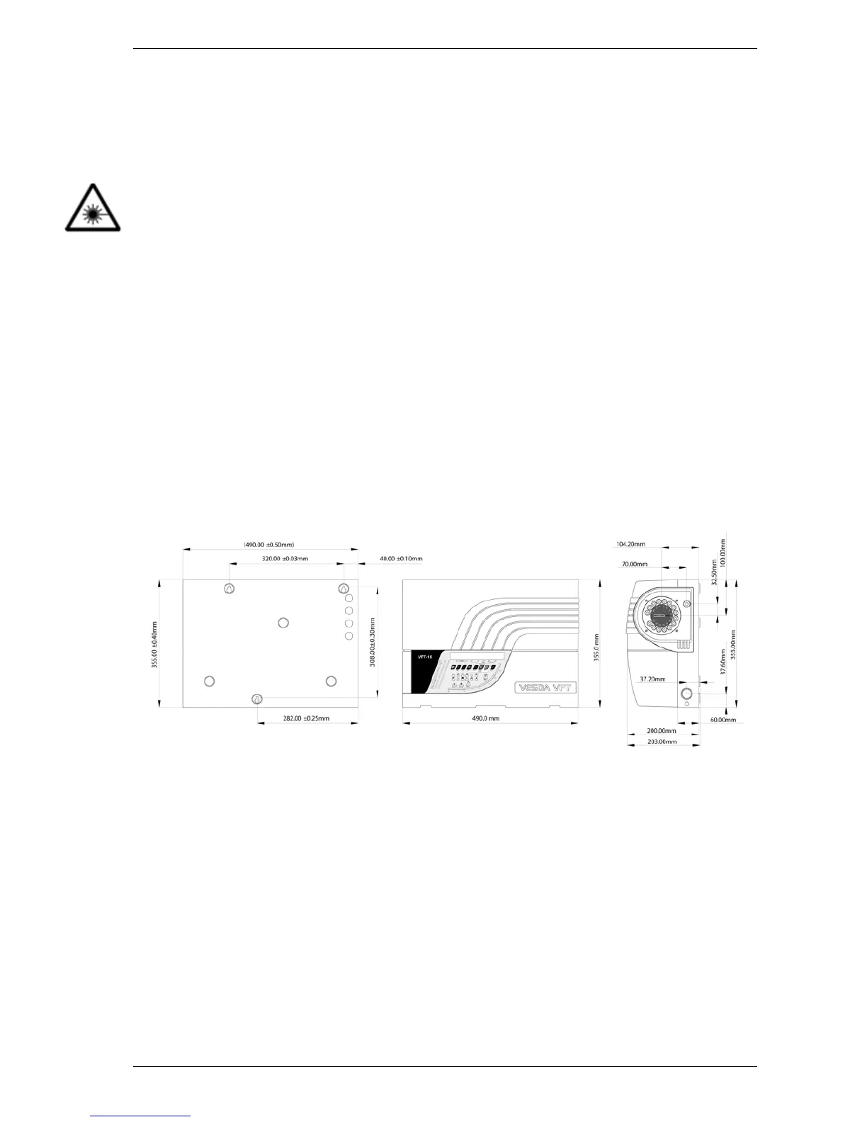
1. Securely mount the back box to a suitable wall or support using the three points shown in the fixing
diagrams in Section 3.1. M6 or M8 screws are suitable.
2. Connect the cables for the power supply and any I/O modules. Ferrite cores should be fitted to the
power cable.
3. Fit the microbore tubes to the system. For details on how to design and install a pipe network, refer to
Appendix B.
3.1 Mounting the Detectors
Careful consideration should be given to the mounting location of the detector to ensure that it is:
l Positioned at an accessible height to facilitate commissioning, routine testing and maintenance.
l Positioned in an area where the exhaust air pipe will remain clear of obstacles at all times.
l Not installed above a heat source such as a radiator or in direct air flow source such as Air
Conditioners.
l Secure and free from operation by unauthorized personnel.
Figure 3-1: VFT-15 Mounting Diagram and Dimensions

 Loading...