VESDA VFT Product Guide
VESDA by Xtralis
18 www.xtralis.com
3.3 Microbore Connections
Note: For more details refer to the VESDA Pipe Installation Guide or Appendix B.
The VFT detectors require microbore, which is 6 mm (0.24 in) OD and 4mm (0.16 in)ID flexible tube. The
length of the tubes must be 50 m (164 ft). Excess tubing must be coiled close to the sampling point end. Other
materials may be used such as FEP or Stainless Steel with suitable adaptors for harsh environments. Ensure
that microbore tubes are never glued to the inlets of the detector.
Unused inputs on the detectors should be looped to one another using short lengths of microbore. For
example, if the VFT-15 detector has unused inputs 9 to 15, one way of connecting the unused inputs would be
to use short pieces of microbore to connect inputs 9 to 12, 10 to 13, 11 to 14 and have input 15 capped off.
Caution: Do not insert ANY object into the inlet ports other than the correct size of piping. This is to avoid
damage to delicate electronic flow sensor components mounted just inside each port opening.
3.4 Remote Display Panel
An installation kit is available for mounting a display panel up to 1 km away from the detector. It contains:
l 1 Blanking plate
l 1 Mounting Box
l 1 Fixing kit
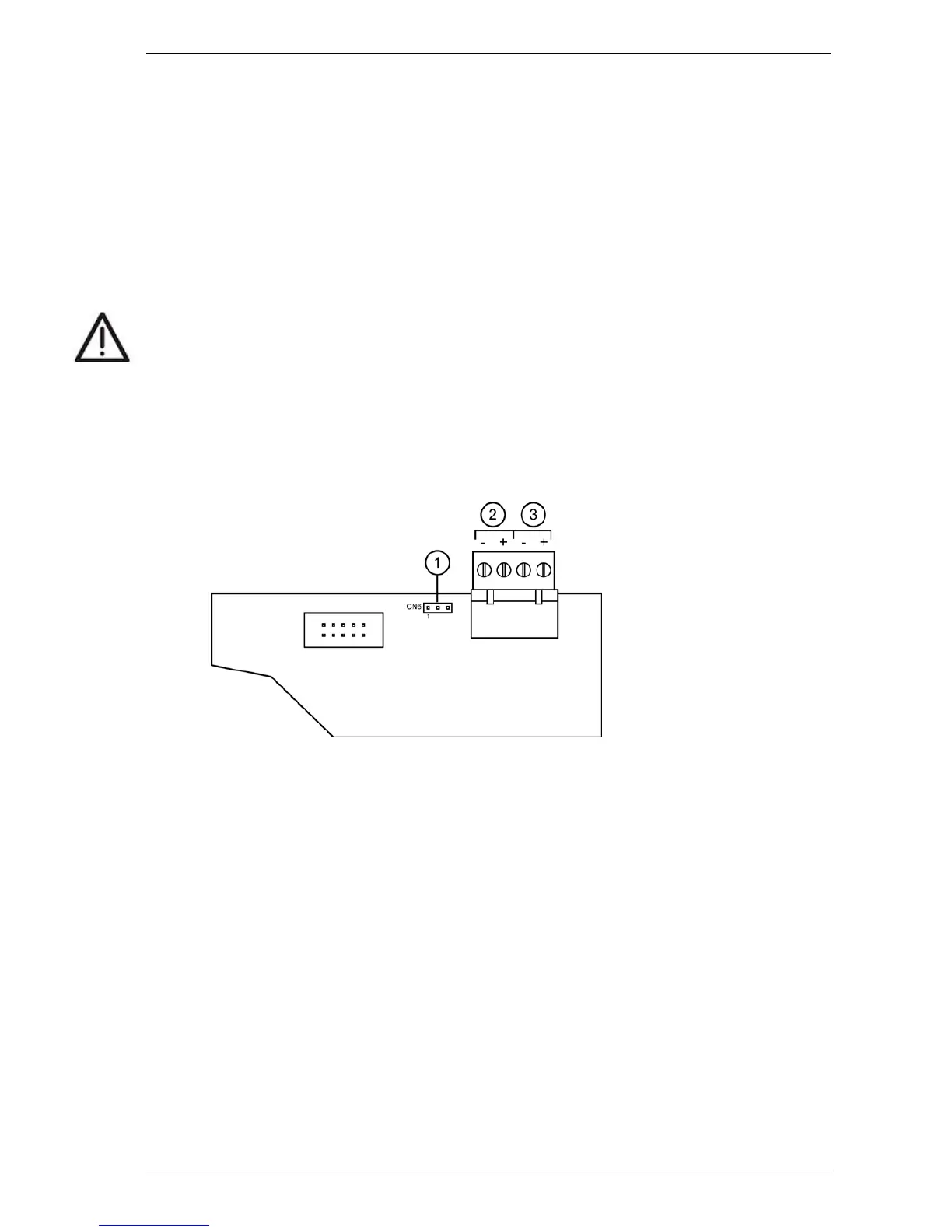
1. Jumper Link
2. RS485
3. 24 VDC power
Figure 3-4: Display board and terminal for remotely connecting the Display Panel
Note: Ensure that a jumper link is fitted across pins 1-2 on CN 6.
Suitable 2 pair twisted pair cable (e.g. Belden 9842) for connecting RS485 communications and 24 VDC
power must be used. More information may be found in Section D.4. Ensure that the electrical characteristics
of the cable connected are appropriate for the distance between the detector and display module.
When using the cable, use one pair for RS485 communications, the other pair for 24 VDC supply, and ensure
that matching signals are connected at each end.
To use the Display Panel remotely, the main unit must also be configured for remote display operation by
following these steps (refer to Figure 5-1 for User Function buttons):
1. Press MENU
2. Use Parameter UP & DOWN to reach SETUP (Scan and Isolate buttons)
3. Press ENTER
4. Enter Level 2 Access Code (693) - refer to Section 5.1 for details on the Access Code
5. Use Parameter UP & DOWN to reach REMPANEL
6. If the display shows REMPANEL 0 then press Value UP to get REMPANEL 1
7. Press ENTER
8. Press MENU twice to revert to normal operation

 Loading...