VESDA VFT Product Guide
VESDA by Xtralis
34 www.xtralis.com
5.4 Input-Output Modules
VFT detectors have 5 relays fitted as standard. The I/O functionality may be extended by adding I/O modules.
These plug onto the standard I/O module in a stackable chain of up to 5. They are recognized by the processor
as Modules 1 to 5 going from left to right. When installing new modules, the type must be entered in the Setup
menu in order to be correctly recognized. Some modules, such as the 4 Channel Relay Module, can be
individually programmed under Configuration mode.
5.4.1 4-Channel Relay Module
There are three steps to configuring a relay module:
1. After installing the relay module check that MODn (n = module position) in the Engineering menu has
now changed to RELAY 4.
2. In Setup menu, change MODn to RELAY 4.
3. In the Configuration menu, set MODn triggering event required:
l Alert
l Action
l Fire1
l Fire2
l Flow fault
l General Fault
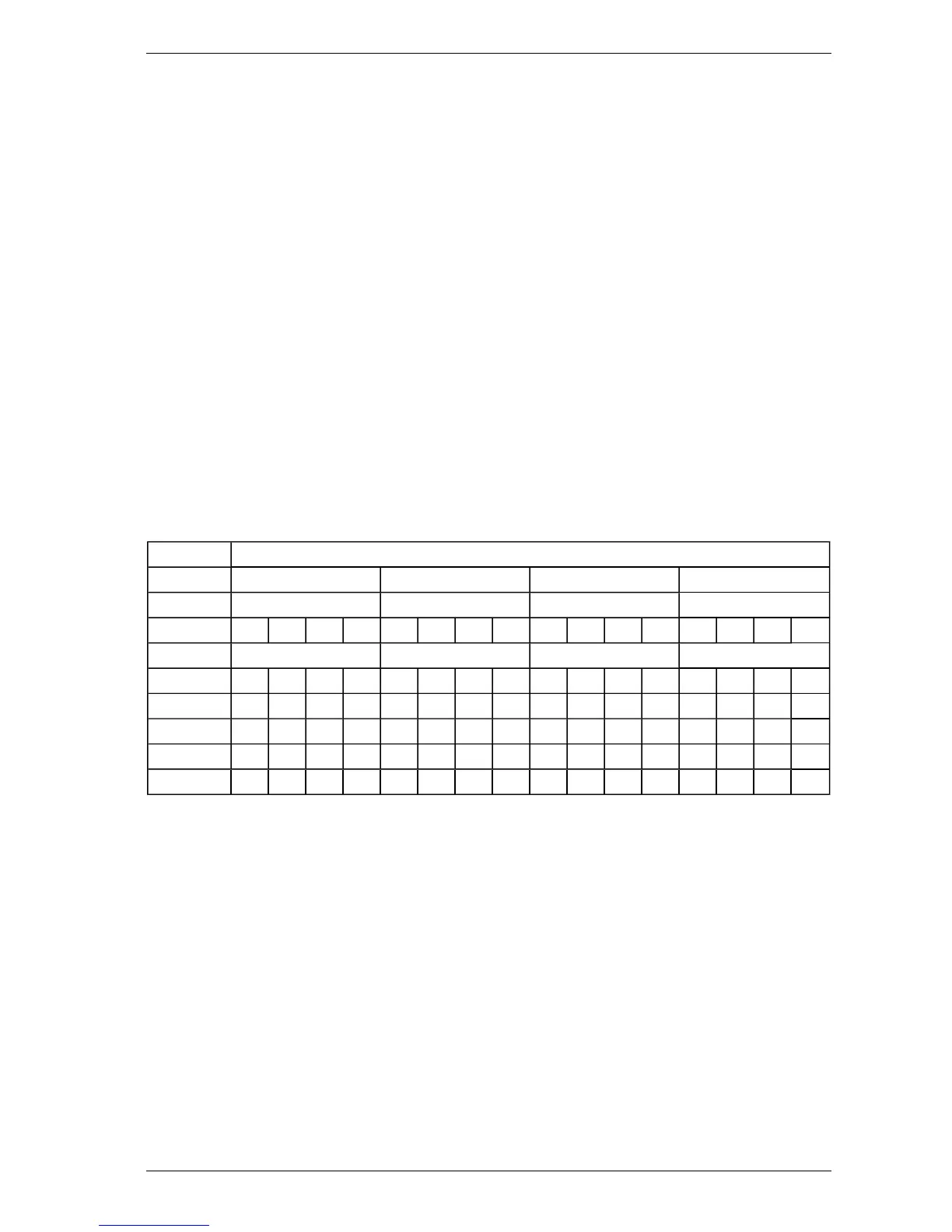
All four relays on the card will now activate for this event with respect to their corresponding sector. The
following table shows how relay cards will be setup when using one or more modules.
Table 5-9: Relay Module Set-up Table
Relay Module
1 2 3 4
Relay Relay Relay Relay
1 2 3 4 1 2 3 4 1 2 3 4 1 2 3 4
Config Sector Sector Sector Sector
Alert 1 2 3 4 5 6 7 8 9 10 11 12 13 14 15 -
Action 1 2 3 4 5 6 7 8 9 10 11 12 13 14 15 -
Fire 1 1 2 3 4 5 6 7 8 9 10 11 12 13 14 15 -
Fire 2 1 2 3 4 5 6 7 8 9 10 11 12 13 14 15 -
Flow 1 2 3 4 5 6 7 8 9 10 11 12 13 14 15 -

 Loading...