VESDA by Xtralis
VESDA VFT Product Guide
www.xtralis.com 61
F UL/ULC wiring requirements for Fire Alarm
connection application
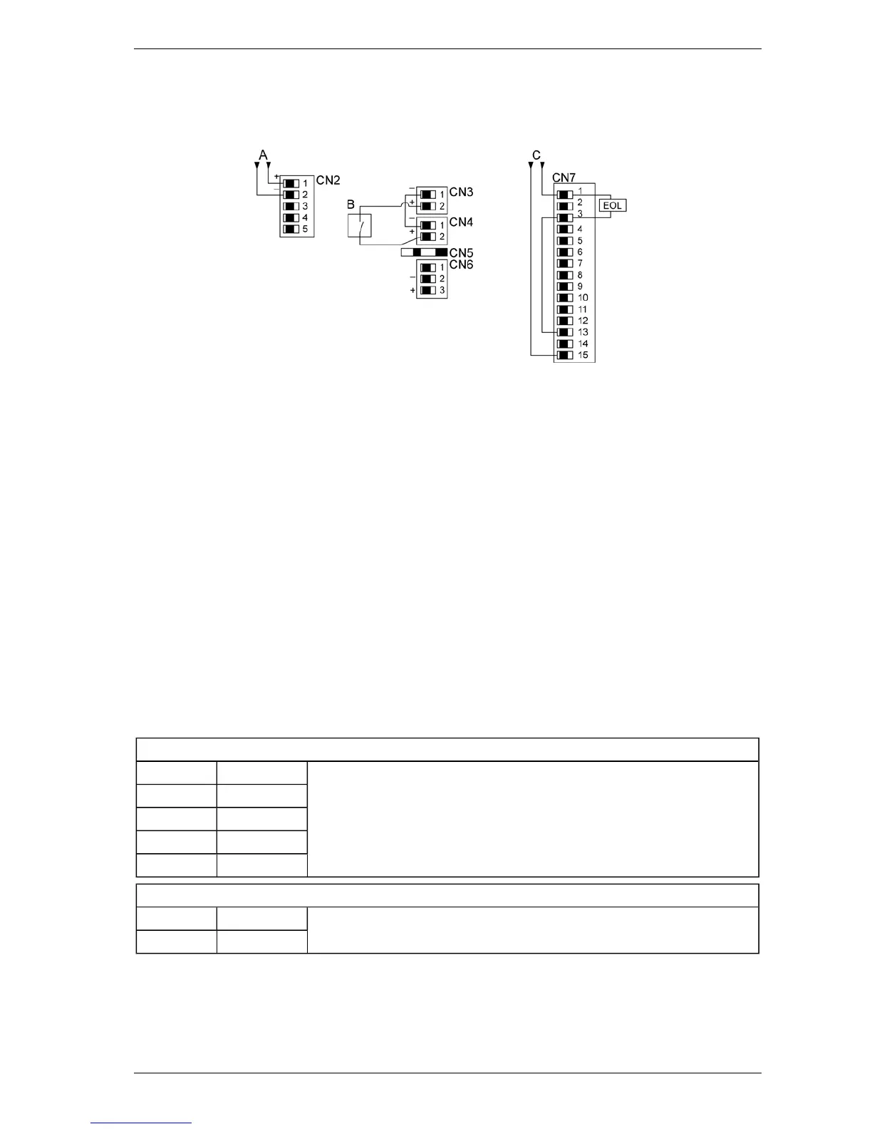
Figure F-1: ULC input and output requirements
1. 24 VDC input power applied to terminals 1 & 2 of CN2 as shown in item A above. 24 VDC supply shall
be a ULC-527 Listed Fire Alarm Control Panel or ULC-527 Listed power supply.
2. For connection to Analog addressable systems - monitoring of Alarm and Fault relay outputs are to be
connected as item C above (as a minimum). Optionally, there are an additional 3 relay outputs
corresponding to thresholds - Alert, Action and Fire 2 which can be monitored also. Additional
addressable contact monitoring devices would be used to monitor those output contacts as needed.
3. For Conventional Initiating device circuits – wiring of alarm and fault contacts shall be wired as shown
in item C above (as a minimum. Optionally there are 3 additional thresholds available (Alert, Action &
Fire 2) which can be monitored also. These would require the use of additional Initiating circuits from
the conventional control panel.
4. Additionally in either case above (Addressable or conventional interfaces) a remote reset input is
required to reset latched Alarm and Fault conditions on the unit. An external reset device would be
connected between CN3 & CN4 terminals as shown in item B above. This input will reset when the fire
alarm control panel is reset clearing all latched Faults and Alarms.
5. Installation of detectors shall meet all applicable requirements of the following:
a. Standard for the Installation of Fire Alarm System - CAN/ULC-S524
b. National Building Code of Canada.
c. National Fire Code of Canada
Table F-1: Connections for i602 I/O Board
CN2: DC Supply
1 24 VDC in Requires 16 x 0.25-15 A (18 AWG) cable (0.75mm
2
minimum IEC60227 H05
W-F/H05 WH2-F2 for EC).
Note: Link Pin 2 (0 V) and Pin 5 (MAINS/BAT). Refer to page 13 for further
details.
2 0 VDC in
3 N/C
4 N/C
5 Mains/Battery
CN4: Remote Reset Interface
1 - input Opto isolated input. 24 VDC low current signal.
2 + input

 Loading...