
Do you have a question about the Xylem HYDROVAR HV2.1f and is the answer not in the manual?
| Model | HYDROVAR HV2.1f |
|---|---|
| Frequency | 50/60 Hz |
| Output Current | 2.1 A |
| Control Method | Sensorless Vector Control |
| Communication Protocols | Modbus RTU |
| Humidity | Max. 95% non-condensing |
Guidelines for safe transport, handling, storage, and disposal of the HYDROVAR unit.
Specifies the type and minimum volume for diaphragm pressure tanks.
Details ambient temperature, storage, humidity, air pollution, and altitude limits.
Lists standards for electromagnetic compatibility and interference suppression.
Provides physical dimensions and weight for various HYDROVAR models.
Details standard mounting hardware and optional accessories.
Information on bus interfaces, sensors, filters, and motor cables.
Step-by-step guides for mounting the HYDROVAR on the motor.
Covers protective measures like earthing, RCDs, and EMC best practices.
Details internal wiring and connection points for different models.
Illustrates main voltage terminal connections for various series.
Instructions for connecting the motor and mounting the PTC.
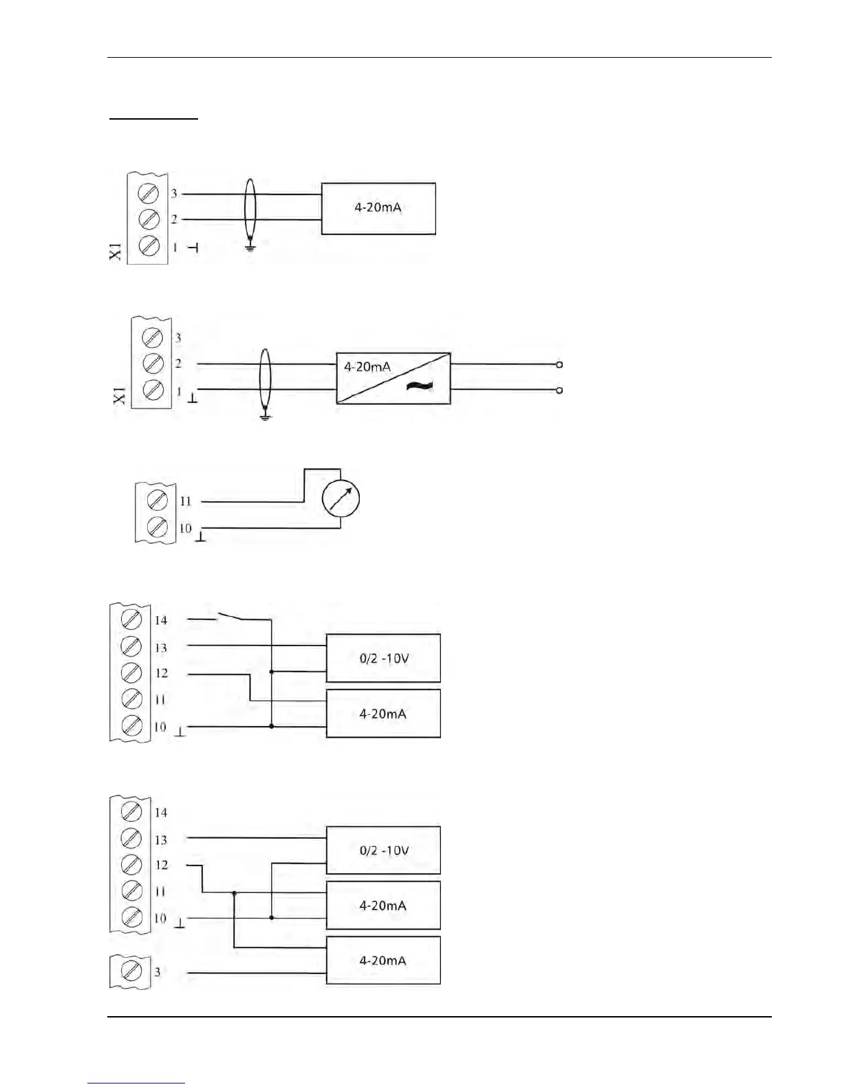
Explains the functions and connections of control and RS485 terminals.
Guides on selecting switching frequency and reducing output current.
Explains the RFI switch for filter activation and its implications.
Overview of the control panel, button functions, and language selection.
Details Controller, Actuator, Multicontroller, and Manual modes.
Covers error memory, total run time, and saving parameters.
Manual operation, ramp settings for acceleration and deceleration.
Defines bands for switching between slow and fast ramps.
Sets acceleration and deceleration times for ramps 1-4.
Configures maximum/minimum frequency and sensor range.
Settings for operation at minimum frequency and motor boost.
Procedures for sensor adjustment, curve selection, and range setting.
Selects operating mode: Controller, Multicontroller, Synch. Controller, Actuator.
Manual control, regulation modes (Normal/Inverse), and start value.
Sets a secondary required value and its input source.
Configures pump relay and offset input source.
Sets levels and intensities for offset calculation.
Illustrates offset calculation with example values.
Manages multi-pump operation, sequence control values.
Enables sequence control, sets switch interval, and source of required value.
Manages synchronous control, limits, and windows for multi-pump systems.
Shows pump status and diagnostic counters for communication.
Configuration for RS485 interface, pump addresses, and ADC reference.
Controls pressure increase based on system curve and lift amount.
Configures analogue output, dimension units, and automatic test runs.
Settings for performing manual test runs, including frequency and boost.
Accesses error memory, limits, delay times, and reset options.
Settings for operating hours, display contrast, password, lock function, and heater.
Resets settings to defaults and saves parameter changes.


