13FT-857 Operating Manual
rest of the vehicle’s body, using a heavy braid bonded securely at both ends, to ensure that as
much counterpoise as possible is secured. In portable operation, be sure to lay out radials (or
otherwise construct a n image plane for the vertical monopole); it is not adequate simply to
connect a vertical radiating element to the rear panel Antenna jack of this transceiver, with-
out providing a suitable counterpoise.
Base Station Antenna Installations
When installing a “balanced” antenna such as a Yagi or dipole, remember that the FT-857 is
designed for use with an (unbalanced) coaxial feedline. Always use a balun or other balanc-
ing device so as to ensure proper antenna system performance.
Use high-quality 50 W coaxial cable for the lead-in to your FT-857 transceiver. All efforts at
providing an efficient antenna system will be wasted if poor quality, lossy coaxial cable is
used. Losses in coaxial lines increase as the frequency increases, so a coaxial line with 0.5
dB of loss at 7 MHz may have 6 dB of loss at 432 MHz (thereby consuming 75% of your
transceiver’s power output!). As a general rule, smaller-diameter coaxial cables tend to have
higher losses than larger-diameter cables, although the precise differences depend on the
cable construction, materials, and the quality of the connectors used with the cable. See the
cable manufacturer’s specifications for details.
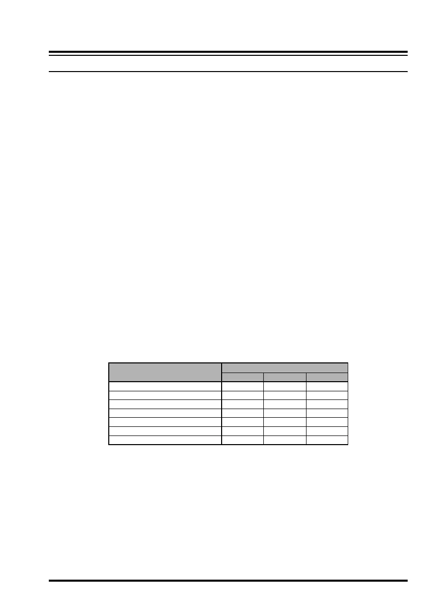
For reference, the chart below shows approximate loss figures for typically- available co-
axial cables frequently used in HF installations.
Loss in dB per 30 m (100 feet) for Selected 50-ohm Coaxial Cables
INSTALLATION
ANTENNA CONSIDERATIONS
CABLE TYPE
RG-58A
RG-58 Foam
RG-8X
RG-8A, RG-213
RG-8 Foam
Belden 9913
7/8” “Hardline”
1.8 MHZ
0.55
0.54
0.39
0.27
0.22
0.18
< 0.1
LOSS
28 MHZ
2.60
2.00
1.85
1.25
0.88
0.69
0.25
432 MHZ
>10
8.0
7.0
5.9
3.7
2.9
1.3
Loss figures are approximate; consult cable manufacturer’s cata-
logs for complete specifications.
Always locate antennas such that they can never come in contact with outdoor power lines in
the event of a catastrophic support or power-pole structural failure. Ground your antennas’
support structure(s) adequately, so as to dissipate energy absorbed during a lightning strike.
Install appropriate lightning arrestors in the antenna coaxial cables (and rotator cables, if
rotary antennas are used).
In the event of an approaching electrical storm, disconnect all antenna lead-in, rotator cables,
and power cables completely from your station if the storm is not immediately in your area.
 Loading...