Transmitting
Operation
0
Listen carefully on the frequency to make sure
you will not interfere with any other stations.
Then, if you have an automatic antenna tuner
option, press
START
to match the antenna.
0
After
"WAIT"
disappears from the display
press the
PTT
(push-to-talk) switch on your
microphone, and give your
callsign (to iden-
tify your transmission) or make your call. You
should see the meter fluctuate as you speak.
Note:
Adjusting the
MIC
control for proper ALC
indication on the meter requires that the SWR be
below
1.5:l. Otherwise the ALC meter may be-
have erratically.
0
To find the optimum setting of the
MIC
control
for your microphone, begin with it fully coun-
terclockwise (minimum), and adjust it while
the
RF PWR
control is fully clockwise. Speak
into the microphone (at a normal level) so that
the meter deflects no further than mid-range
(the upper end of the blue ALC range) on
voice peaks. This will normally be about the
10-o'clock position with the
MH-1138 or MD-
la
microphone.
0
You can press the
PO
button/LED and adjust
the
RF PWR
control for less output power, as
indicated on the second meter scale from the
top. We recommend using the lowest power
output possible to maintain reliable commu-
nications
-
not only as a courtesy to other
stations, but to minimize power consumption
and the possibility of causing
RFI and TVI,
and to maximize the life of the equipment.
Microphone Tone Selection
Before setting up the speech processor, set the
selector switch on your microphone for the de-
sired audio characteristic. The higher-numbered
setting(s) suppress low frequencies. See page
5.
AF
Speech Compressor
Once you have found the proper
MIC
control
setting (with full power) and selected the micro-
phone tone characteristic, you can activate the
speech compressor to increase the average
power of your signal. The
RF PWR
setting does
not affect speech processor
ad.justment.
0
Press the
ALC
button/LED, and the
PROC
but-
ton just below it, so that the
LEDs in both
buttons light. Now speak into the microphone
and adjust the
MIC
control slightly, if neces-
sary, so the meter needle stays within the
thick blue ALC zone on the bottom scale.
0
The
COMP
control on the rear panel (the shaft
nearest the antenna jack) sets the degree of
compression. This control is preset to the 12-
o'clock position at the factory, which provides
about 10 dB of speech compression with an
average voice pitch. Setting it for more com-
pression can seriously distort your signal, so
it should only be adjusted if you have some
means of monitoring the transmitter. You can
do this with an external receiver, if you have
IF
Processor Frequency
Shift
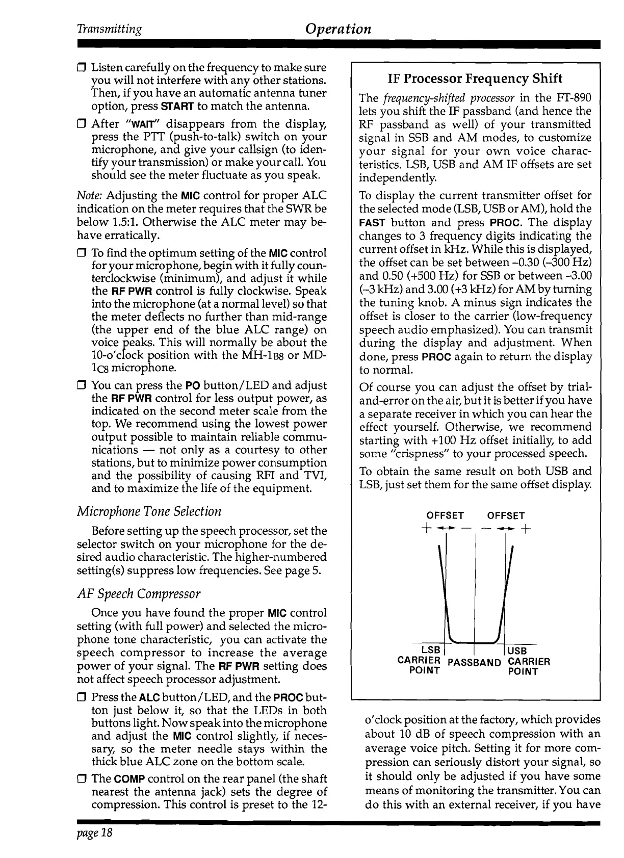
The
frequency-shifted processor
in the FT-890
lets you shift the
IF
passband (and hence the
RF
passband as well) of your transmitted
signal in SSB and AM modes, to customize
your signal for your own voice charac-
teristics. LSB, USB and AM IF offsets are set
independently.
To display the current transmitter offset for
the selected mode (LSB, USB or AM), hold the
FAST
button and press
PROC.
The display
changes to 3 frequency digits indicating the
current offset in kHz. While this is displayed,
the offset can be set between -0.30 (-300 Hz)
and 0.50
(+500 Hz) for SSB or between -3.00
(-3 kHz) and 3.00 (+3 kHz) for AM by turning
the tuning knob.
A
minus sign indicates the
offset is closer to the carrier (low-frequency
speech audio emphasized). You can transmit
during the display and adjustment. When
done, press
PROC
again to return the display
to normal.
Of course you can adjust the offset by trial-
and-error on the air, but it is better if you have
a separate receiver in which you can hear the
effect yourself. Otherwise, we recommend
starting with
+I00 Hz offset initially, to add
some "crispness" to your processed speech.
To obtain the same result on both USB and
LSB, just set them for the same offset display.
OFFSET OFFSET
+--
--+
page
18
US6
LSB
CARRIER PASSBAND CARRIER
POINT PO
l NT
\
 Loading...