Operation
Digital
Modes
could do it the other way too). Also recall that
Digital
Modes
we must change to the memory tune mode to
copy one
megory to another.
SO,
by pressing
the
AIB
button now, we can accomplish two
things at once: the low edge (15.100 MHz)
stored in the rear of the memory comes to the
front, and the memory tune function is acti-
vated
("MEM"
is replaced by
"M
TUNE"
at the
left).
0
Now press
VFOtM
momentarily to activate
memory checking, and press
the
UP
button to
display memory
PI. Then hold
VFOcM
for
'h
second to write memory 19 to memory PI.
That takes care of the low edge, and also shifts
operation to memory
P1 with memory tuning
activated.
0
Press
AIB
to select the other half of memory
PI, which now holds the high band edge (cop-
ied from memory 19 in the last step).
0
Press
VFOtM
momentarily to activate mem-
ory checking, and press the
LIP
button to dis-
play memory
P2.
Then hold
VFOcM
for
'h
second to write memory PI (with front and
back reversed) to memory
P2.
That stores the
high edge into the front of memory
P2, and
leaves operation in the memory tuning mode
on memory P2: just where we want to be.
Now when you tune or scan, operation re-
mains within the 15.100- to 15.600-MHz range.
The
lT-890 offers a few special features for
digital modes, such as the
DATA INIOUT
jack on
the rear panel, and a very fast transmit-to-re-
ceive turnaround time. This provides good per-
formance on 1200-baud packet above 29 MHz.
Unfortunately, optimum
AMTOR, RTTY and
300-baud packet operation is difficult, because
the optional 500-Hz narrow CW filter is not
available for reception in the SSB modes needed
for AFSK transmission. You can keep operation
simple (and avoid the need for the 500-Hz CW
filter option) by using the LSB mode with its
2.4-kHz bandwidth for both transmission and
reception, but the broad receiver
IF
bandwidth is
not optimum for receiving narrow-shift AFSK.
Alternatively, if you have the 500-Hz CW filter
installed, you can try using it for reception in CW
mode and transmitting in
an
SSB mode; but this
requires offsetting your transmit and receive fre-
quencies, along with a few other niggles.
TUITNC
Interconnections
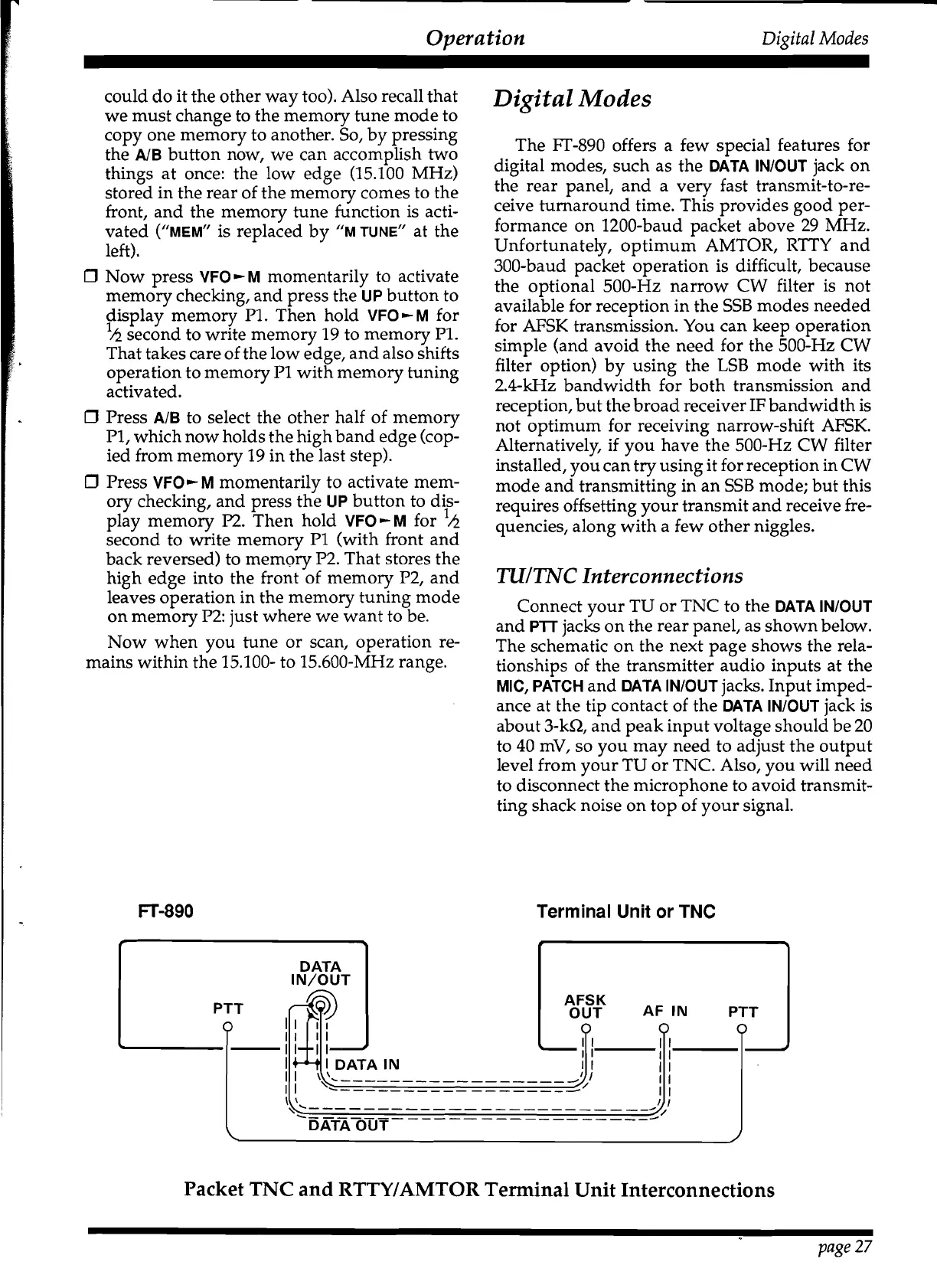
Connect your TU or TNC to the
DATA INIOUT
and
P'TT
jacks on the rear panel, as shown below.
The schematic on the next page shows the rela-
tionships of the transmitter audio inputs at the
MIC, PATCH
and
DATA INIOUT
jacks. Input imped-
ance at the tip contact of the
DATA INIOUT
jack is
about
3-kR, and peak input voltage should be 20
to 40
mV, so you may need to adjust the output
level from your TU or TNC. Also, you will need
to disconnect the microphone to avoid transmit-
ting shack noise on top of your signal.
FT-890
Terminal Unit or
TNC
r
+
DATA
IN/OUT
I
I
I1
II
I
I
I
IDATAIN
I
I
II
\'.-----------------
,:/
I
I
'-
-----------------
-
I
I
I I
'<.-
--
-
- -
-
-
-
-
- -
-
-
-
-- --
-
-
-
-
-9,
I
I
--
-
-
--
--
-
--
-
-
-
-
-
-
-
--
-
-
---/
\
DATA OUT
J
Packet
TNC
and
RTTYIAMTOR
Terminal Unit Interconnections
page
27
 Loading...