3
?-2
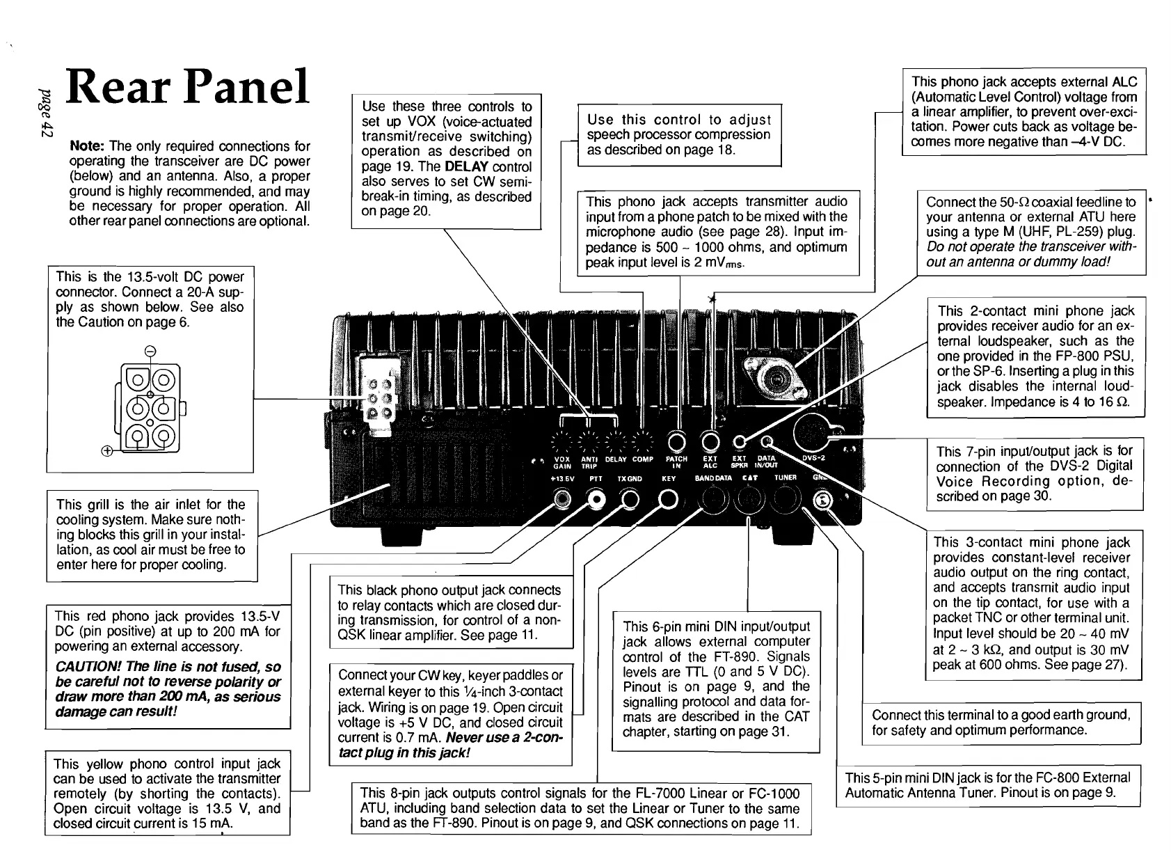
Rear Panel
lb
h,
Note:
The only required connections for
operating the transceiver are DC power
(below) and an antenna. Also, a proper
ground is highly recommended, and may
be necessary for proper operation. All
other rear panel connections are optional.
This is the 13.5-volt DC power
connector. Connect a 20-A sup-
ply as shown below. See also
the Caution on page 6.
This grill is the air inlet for the
cooling system. Make sure noth-
ing blocks this grill in your instal-
lation, as cool air must be free to
enter here for proper cooling.
k
This red phono jack provides 13.5-V
DC (pin positive) at up to 200
mA
for
powering an external accessory.
CAUTION!
The
line is not fused, so
be careful not to reverse polarity or
draw more than
200
mA, as serious
damage can result!
remotely (by shorting the contacts).
Open circuit voltage is 13.5 V, and
closed circuit current is 15
mA.
Use these three controls to
set up VOX (voice-actuated
transmitlreceive switching)
operation as described on
page 19. The
DELAY
control
also serves to set CW
semi-
break-in timing, as described
on page 20.
Use this control to adjust
speech processor compression
as described on page 18.
This phono jack accepts transmitter audio
input from a phone patch to be mixed with the
microphone audio (see page 28). lnput im-
pedance is 500
-
1000 ohms, and optimum
peak input level is 2
mVms.
This phono jack accepts external ALC
(Automatic Level Control) voltage from
a linear amplifier, to prevent
over-exci-
tation. Power cuts back as voltage be-
comes more negative than -4-V DC.
Connect the 50-R coaxial
feedline to
'
your antenna or external ATU here
using a type
M
(UHF, PL-259) plug.
Do not operate the transceiver with-
out an antenna or dummy load!
1
This black phono output jack connects
to relay contacts which are closed dur-
1
i
jack. Wiring is on page 19. Open circuit
voltage is
+5 V DC, and closed circuit
current is 0.7
mA.
Never use a 2-con-
ing transmission, for control of a non-
QSK linear amplifier. See page 11.
control of the FT-890. Signals
levels are
TTL (0 and 5 V DC).
Pinout is on page 9, and the
signalling protocol and data for-
mats are described in the CAT
chapter, starting on page 31.
Ill
This 6-pin mini DIN input/output
jack allows external computer
tact plug in this jack!
I
I
I
I
I
This 8-pin jack outputs control signals for the FL-7000 Linear or FC-1000
I
ATU, including band selection data to set the Linear or Tuner to the same
band as the FT-890. Pinout is on page 9, and QSK connections on page 11.
This 2-contact mini phone jack
provides receiver audio for an ex-
ternal loudspeaker, such as the
one provided in the FP-800 PSU,
or the SP-6. Inserting a plug in this
jack disables the internal loud-
speaker. Impedance is
4
to 16 R.
I
This 3-contact mini ~h0ne iack
I
provides constant-level receiver
audio output on the ring contact,
and accepts transmit audio input
on the tip contact, for use with a
packet TNC or other terminal unit.
lnput level should be 20
-
40 mV
at 2
-
3
kQ,
and output is 30 mV
peak at 600 ohms. See page 27).
Connect this terminal to a good earth ground,
for safety and optimum performance.
This 5-pin mini DIN jack is for the FC-800 External
Automatic Antenna Tuner. Pinout is on page 9.
 Loading...