Installing Internal Accessories
0
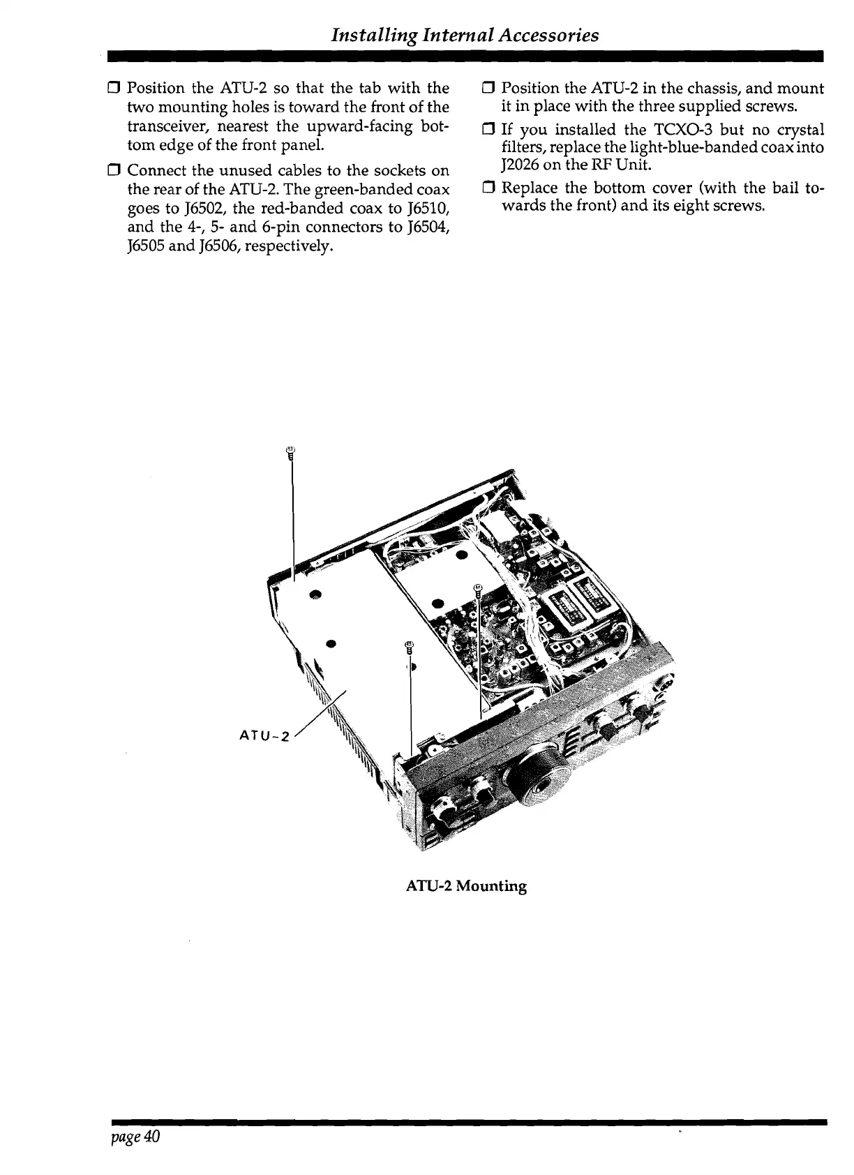
Position the ATU-2 so that the tab with the
0
Position the ATU-2 in the chassis, and mount
two mounting holes is toward the front of the
it in place with the three supplied screws.
transceiver, nearest the upward-facing bot-
0
1f
you installed the
TCXO-3
but no clystal
tom edge of the front panel.
filters, replace the light-blue-banded coax into
0
Connect the unused cables to the sockets on
J2026 on the
RF
Unit.
the rear of the ATU-2. The green-banded coax
0
Replace the bottom cover (with the bail to-
goes to J6502, the red-banded coax to J6510,
wards the front) and its eight screws.
and the
4-,
5- and 6-pin connectors to J6504,
J6505 and J6506, respectively.
ATU-2
Mounting
page
40
 Loading...