Installing Internal Accessories
Optional
IF
Crystal Filters
The 500-Hz YF-100 or 250-Hz XF-455K-251-01
crystal filters may be installed for
CW
narrow
reception, and the YF-101 2.6-kHz crystal filter
may be installed for improved
SSB
and AM nar-
row receiver selectivity.
0
If you haven't already, perform the first six
steps under
Cover Removal
at the start of this
chapter.
0
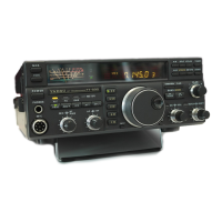
Referring to the photos at the right, determine
the
location(s) of the filter(s) you are installing
(the
YF-100 and XF-455K-251-01 cannot both
be installed, as they use the same mounting
location). If installing either filter for CW nar-
row, remove the jumper plug indicated in the
upper photo at the right.
0
If installing the YF-101 for
SSB
and AM nar-
CW Filter, Jumper
&
Ceramic
SSB
Filter
Jumper Plug Ceramic
SSB
filter
row, lift th: rear edge of the board and care-
fully unsolder and remove the ceramic filter.
SSB
Filter Location (replacing Ceramic Filter)
0
Straighten the new filters' leads, if necessaw.
~he<~osition each filter as indicated in tfie
photos, and push the filter leads through the
board.
0
Lift the rear edge of the board and solder each
filter lead on the solder side of the board while
holding the filter snug against the board.
Then clip off any excess leads. Check your
solder joints carefully.
0
Replace the board in the chassis, using care to
avoid pinching any wires.
0
Replace the six screws removed from the
RF
Unit (Figure 2), and replace the coaxial cables
(#1
and #2 in Figure 2): the yellow-banded
cable goes in
J2024, and the light-blue-banded
cable goes in
J2026.
0
Referring to Figure 3C, replace the ribbon ca-
ble into its connector, and press down firmly
on both sides of the socket while pressing the
ribbon cable into the socket. Confirm that it is
firmly in place.
O
Unless installing the ATU-2, replace the bot-
tom cover (bail towards the front) and its
eight screws.
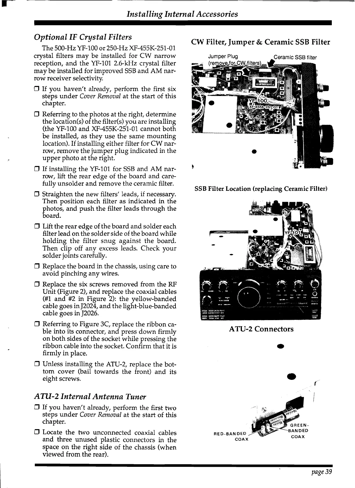
ATU-2 Internal Antenna Tuner
0
If you haven't already, perform the first two
steps under
Cover Removal
at the start of this
chapter.
0
Locate the two unconnected coaxial cables
and three unused plastic connectors
in
the
space on the right side of the chassis (when
viewed from the rear).
ATU-2
Connectors
*
page
39
 Loading...