CAT
System Computer Control
All
649
Bytes of Status Update Data (Sent L-to-R)
Flags
M
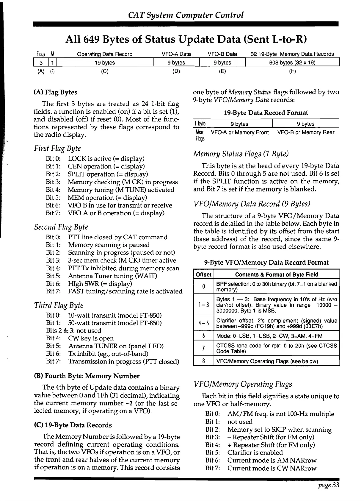
Operatiqg Data Record VFO-A Data VFO-B Data 32 19-Byte Memory Data Records
First Flag Byte
Bit 0:
LOCK is active
(=
display)
Bit 1:
GEN operation
(=
display)
Bit 2:
SPLIT operation
(=
display)
Bit 3:
Memory checking
(M CK) in progress
Bit 4:
Memory tuning
(M
TUNE)
activated
Bit 5:
MEM operation
(=
display)
Bit 6:
VFO
B in use for transmit or receive
Bit
7:
VFO
A or B operation
(=
display)
(A)
Flag Bytes
one byte of
Memo
y
Status flags followed by two
The first 3 bytes are treated as 24 1-bit flag
9-byte
VFOIMemo
y
Data records:
fields: a function is enabled (on) if a bit is set
(I),
19-Byte Data Record Format
and disabled (off) if reset
(0). Most of the func-
,
tions represented by these flags correspond to
Second Flag Byte
Bit 0:
PTT line closed by CAT command
Bit 1:
Memory scanning is paused
Bit 2:
Scanning in progress (paused or not)
Bit 3: 3-sec mem check
(M
CK)
timer active
Bit 4:
FTT Tx inhibited during memory scan
Bit 5:
Antenna Tuner tuning (WAIT)
Bit 6:
HIgh SWR
(=
display)
Bit
7:
FAST tuning/scanning rate is activated
608
bytes (32
x
19)
3
111 19 bytes
9 bytes
Third Flag Byte
(A)
(B)
(C)
(Dl
(E)
(F)
9 bytes
Bit
0:
10-watt transmit (model FT-850)
Bit 1: 50-watt transmit (model FT-850)
Bits
2
&
3: not used
Bit 4:
CW
key is open
Bit
5:
Antenna TUNER on (panel LED)
Bit 6: Tx inhibit
(eg., out-of-band)
Bit
7:
Transmission in progress
(PTT
closed)
9
bytes
the radio display.
Mern
VFO-A or Memory Front VFO-B or Memory Rear
Flags
Memory Status Flags
(1
Byte)
9
bytes
This byte is at the head of every 19-byte Data
Record. Bits
0 through
5
are not used. Bit
6
is set
if
the SPLIT function is active on the memory,
and Bit
7
is set if the memory is blanked.
VFOIMemo
y
Data Record
(9
Bytes)
The structure of a 9-byte VFO/Memory Data
record is detailed in the table below. Each byte in
the table is identified by its offset from the start
(base address) of the record, since the same
9-
byte record format is also used elsewhere.
9-Byte
VFOIMemory Data Record Format
Clarifier offset. 2's corn
(B) Fourth Byte: Memory Number
The 4th byte of Update data contains a binary
VFOIMemo
y
Operating Flags
value between 0 and 1Fh (31 decimal), indicating
Each bit in this field signifies a state unique to
the current memory number
-1
(or the last-se-
one VFO or half-memory.
lected memory, if operating on a VFO).
Bit
0: AM/FM freq.
is
not 100-Hz multiple
(C)
19-Byte Data Records
Bit 1: not used
Bit 2:
Memorv set to SKIP when scanning:
"
The Memory Number is followed by a 19-byte
Bit 3:
-
~e~eiter Shift (for FM only)
record defining current operating conditions.
Bit 4:
+
Repeater Shift (for FM only)
That is, the two
VFOs if operation is on a
VFO,
or
Bit
5:
Clarifier is enabled
the front and rear halves of the current memory
Bit 6: Current mode
is
AM NARrow
if operation is on a memory. This record consists
Bit
7:
Current mode
is
CW NARrow
page
33
 Loading...