Do you have a question about the Yamaha CD-S2100 and is the answer not in the manual?
Important warnings and information for service personnel regarding safety and product handling.
Table of contents listing major sections of the service manual.
Information on critical components, leakage current measurement, and safety.
Warning regarding chemical content and guidance on lead-free solder.
Critical safety warnings regarding laser radiation exposure during servicing.
Technical specifications for the laser diodes used in the unit.
Explains laser labels and warns about live mains voltage on the power supply.
Specific notes regarding the handling and adjustment of the loader mechanism.
Detailed guidelines and techniques to prevent damage from static electricity.
Procedures for grounding human body and work tables to prevent ESD.
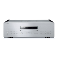
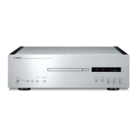
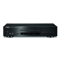
Diagrams identifying front panel controls and indicators for different models.
Diagrams identifying rear panel connectors and labels for U, V, S models.
Diagram of the bottom view and details on model-specific labels.
Diagrams identifying rear panel connectors and labels for T, K, A, B, G, L models.
Diagram identifying rear panel connectors and labels for the J model.
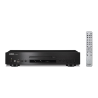
Diagram of remote control layout and audio section technical specifications.
Details on inputs/outputs, sample rates, and general specifications.
Specifications for power supply, list of accessories, and available finishes.
Physical dimensions of the unit with diagrams.
Diagrams showing the internal layout of components.
Safety measures and warnings for servicing, including capacitor discharge.
Specific instructions for using measuring instruments with balanced outputs.
Step-by-step instructions and diagrams for removing side panels and the top cover.
Detailed steps for removing the front panel, including tray manipulation.
Steps for removing the front frame assembly and the main audio printed circuit board.
Steps for removing the disc loading mechanism.
Instructions for correctly installing the loader mechanism unit.
Procedures for adjusting the lid for proper alignment and horizontal position.
Adjusting the lid for equal clearance around the disc tray.
Detailed steps for tray lock, tray push-out, and lid position adjustment.
Steps to remove the DIGITAL, FRONT (1), and FRONT (2)/(8) printed circuit boards.
Detailed steps for removing the power transformers and their supports.
Steps for removing the module board from the loader mechanism.
Step-by-step instructions for removing various loading belts.
Information on when firmware updates are required and the necessary tools.
Steps and warnings before and during the firmware writing process.
Instructions for disconnecting power and setting up the RS-232C conversion adaptor.
Detailed steps for connecting the PC to the unit via RS-232C.
Steps for setting switches, connecting power, and starting the firmware update software.
How to select the firmware file and the correct COM port in the software.
Steps to select the firmware file using the 'Refer...' button.
How to configure the baud rate and other settings in the software.
Steps to erase existing firmware and start writing the new firmware.
Steps to check the written firmware version and disconnect the unit.
Information that firmware must be written after replacing the module board.
Steps for updating firmware using a CD, including creating the CD and performing the update.
Steps to start the firmware writing process and what happens after completion.
How to verify the firmware version after the update.
Introduction to the self-diagnostic functions and menu structure.
List of main menu items available in the diagnostic function.
Procedure for entering the standard self-diagnostic mode.
Procedure for entering self-diagnostic mode with protection functions disabled.
Information on how the protection function history is stored and managed.
Steps to cancel the self-diagnostic function and reset settings.
How to navigate through the main and sub-menus.
Available functions during self-diagnostic mode.
Displays firmware version and checksum.
Shows versions for microprocessor, USB DAC, and module board.
Displays the firmware version of the CPL.
Menu used to check the operation of front panel keys.
How to check individual key operations by pressing them.
Menu to check the operation of the FL display and indicators.
Tests for turning all segments ON/OFF and lighting indicators.
Tests for checking the display dimmer function.
Menu for initializing backup data to factory settings.
Menu to display voltage values related to protection functions.
Details of the L channel power supply protection detection.
Details of the R channel power supply protection detection.
Details of the digital circuit power supply protection detection.
Menu to display the history of protection function activations.
Option to reserve initialization of the protection history.
Checks noted as not for service.
Menu to check the operation of the loader mechanism and disc tray.
Checks the clamp and disc tray opening/closing.
Information regarding display data, pin connections, grid assignment, and anode connections.
Details for the main microprocessor IC, including no replacement part available.
Pin assignments for VCC1/VCC2 ports and detailed microprocessor pin functions.
Detailed functions of specific microprocessor pins.
Detailed functions of specific microprocessor pins.
Detailed functions of specific microprocessor pins.
Information on key detection voltage and pull-up resistance.
Detailed functions of specific microprocessor pins.
Detailed functions of specific microprocessor pins.
Detailed functions of specific microprocessor pins.
Detailed information on key detection voltage and pull-up resistance for AD ports.
A high-level block diagram illustrating the main functional units and their interconnections.
Diagram showing the overall wiring connections between major components.
Wiring diagram specific to the loader mechanism unit.
Component layout for the DIGITAL PCB (Side A).
Component layout for the DIGITAL PCB (Side B).
Component layout for the DIGITAL PCB (Side B).
Component layout for the AUDIO PCB (Side A).
Table listing semiconductor locations on the AUDIO PCB.
Component layout for the AUDIO PCB (Side B).
Table listing semiconductor locations on the AUDIO PCB.
Component layout for the FRONT (1) PCB (Side A).
Safety warnings and semiconductor locations for FRONT (1) PCB.
Component layout for the FRONT (1) PCB (Side B).
Table listing semiconductor locations on the FRONT (1) PCB.
Component layout for the FRONT (2) PCB (Side A).
Safety warnings and semiconductor locations for FRONT (2) PCB.
Component layout for the FRONT (6) PCB (Side A).
Component layouts for FRONT (7) & (8) PCBs (Side A).
Component layout for the FRONT (2) PCB (Side B).
Table listing semiconductor locations on the FRONT (2) PCB.
Component layouts for other FRONT PCBs (Side B).
Component layout for the FRONT (3) PCB (Side A).
Information about key detection via AD ports.
Component layouts for FRONT (4) & (5) PCBs (Side A).
Component layout for the FRONT (3) PCB (Side B).
Component layouts for FRONT (4) & (5) PCBs (Side B).
Pin connection diagrams for ICs, diodes, and transistors.
Schematic showing the digital section's block diagram and details on specific ICs.
Schematic of digital input/output interfaces and related ICs.
Schematic showing the microprocessor (IC404) and associated ICs.
Schematic of main blocks including CPU, A-Bus, Memory, Serial Audio, and Power Supply interfaces.
Details on specific ICs like IC401, IC402, IC403, IC404, IC410, IC413.
Schematic showing the audio section's block diagram and details for audio ICs.
Safety precautions for using measuring instruments with balanced audio outputs.
Schematic details of the audio power supply circuits.
Safety precautions for the audio section, including capacitor discharge.
Schematic showing power and signal routing for the front panel.
Schematic of power supply circuits for the front panel.
Details on specific ICs and components on the front panel.
Schematic of circuits for remote control, system interface, and front panel buttons.
Schematic of power supply and protection circuits on the front panel.
Safety precautions for the front panel circuitry.
Schematic of the IO expander and various indicators on the front panel.
Schematic of circuits for key detection via AD ports.
Visual representation of components on FRONT (3), (4), (5), (6).
Explanation of abbreviations and listing of component part numbers.
List of part numbers for the DIGITAL PCB and its components.
Continuation of the component part numbers for the DIGITAL section.
Part numbers for ICs in the DIGITAL and AUDIO sections.
Part numbers for various components in DIGITAL and AUDIO sections.
List of part numbers for AUDIO components.
Continuation of the part numbers for AUDIO components.
List of part numbers for AUDIO and FRONT components.
List of part numbers for FRONT components.
Continuation of part numbers for FRONT components.
Table listing carbon resistor values and corresponding part numbers.
Exploded view diagram identifying all major parts of the unit.
Detailed list of part numbers and their corresponding descriptions and models.
List of included accessories and service tools.
List of all parts that constitute the loader mechanism unit.
Schematic diagram of the remote control and its panel layout.
Table mapping button names to their corresponding key codes.