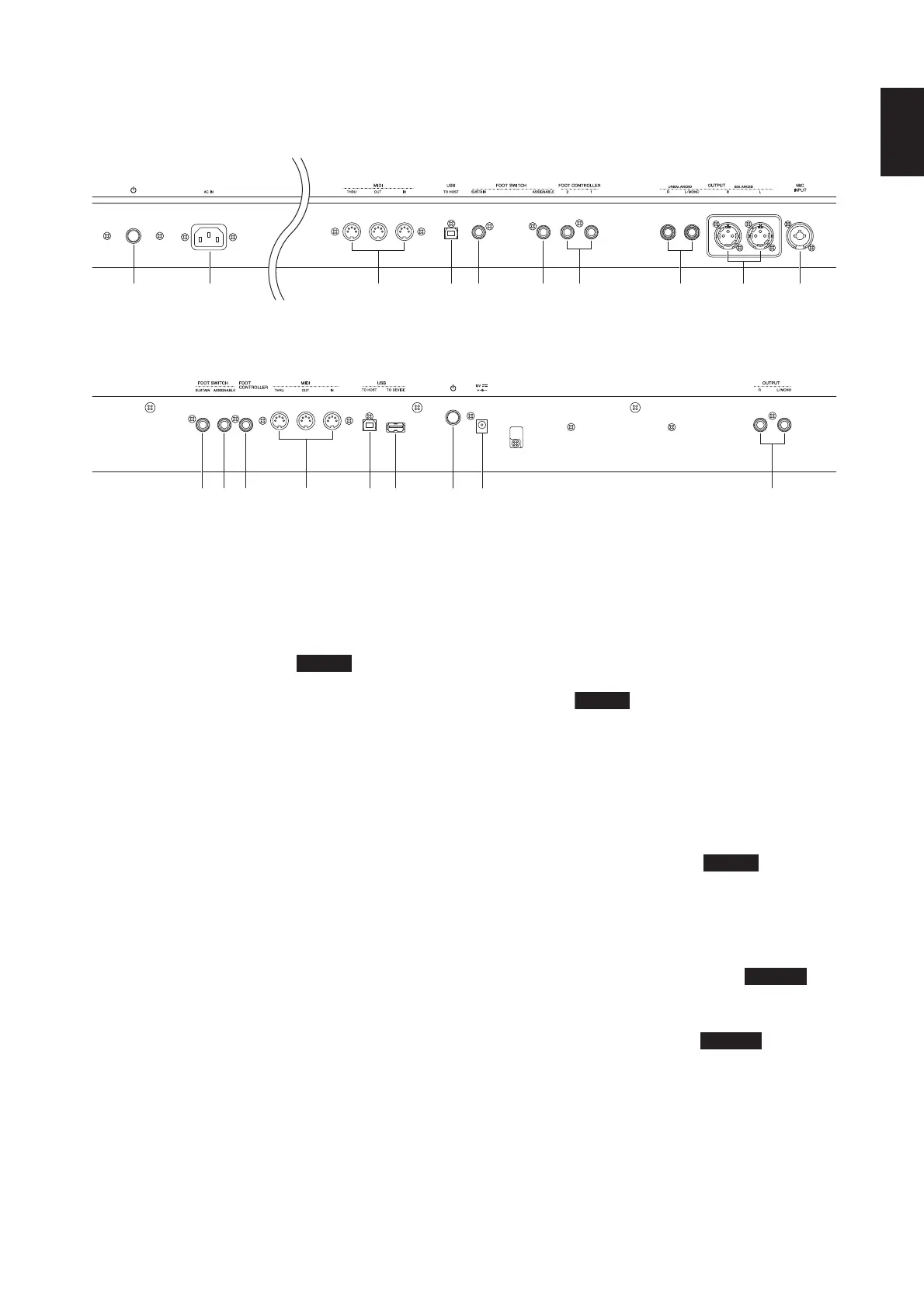
Rear Panel
CP5/CP50 Owner’s Manual
13
Component Names & Functions
Rear Panel
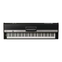
CP5
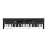
CP50
1 P switch (page 16)
On the CP5, this button is known as the Power switch, and it
is used to turn the stage piano on (O) and off (N). On the
CP50, it is known as the Standby/On switch, and it is used to
set the stage piano to on (O) or Standby mode (N).
2 [AC IN] socket (page 14)
Use this socket to connect the power cord. Note that only the
power cord provided with the CP5 should be used to supply
power.
3 MIDI [IN], [OUT], and [THRU] connectors
(page 45)
Use the three MIDI connectors to link up your CP5 or CP50
with other MIDI devices.
4 [USB TO HOST] port (page 46)
Use this port to connect your CP5 or CP50 to a computer
using a USB cable.
5 [SUSTAIN] foot-switch jack (pages 16, 29)
An optional FC3 foot pedal or an optional FC4 or FC5 foot
switch can be connected via the [SUSTAIN] foot-switch jack
for use as a dedicated sustain pedal.
6 [ASSIGNABLE] foot-switch jack (pages 16, 29)
Use this jack to connect an optional FC4 or FC5 foot switch
in order to perform a range of freely assignable functions.
7 Foot-controller jack(s) (page 16)
Use the foot-controller jack(s) to connect an optional FC7 or
FC9 foot controller in order to perform a range of freely
assignable functions. Note that the CP5 features a pair of
foot-controller jacks, which are labeled [1] and [2], while the
CP50 has single such jack labeled [FOOT CONTROLLER].
8 Unbalanced [L/MONO] and [R] output jacks
(page 15)
These two 1/4" mono phone jacks are used to output
unbalanced stereo signals. Alternatively, if mono output is
required, only the [L/MONO] jack should be connected.
Each connector's nominal output level is +4 dB.
9 Balanced [L] and [R] output connectors
(page 15)
These XLR-type connectors are used to output balanced
stereo signals to mixers and other similar devices. This type
of connector protects signals from interference and has an
extremely sturdy design. It also features a locking
mechanism to prevent cables from being accidentally
disconnected. Accordingly, the XLR connector is regularly
used in professional environments that demand a high level
of reliability. Each connector's nominal output level is +4 dB.
) [MIC INPUT] jack (page 40)
Use this combo jack* to input audio into the CP5. With a
microphone plugged into this jack, you can use the MIC
INPUT part (page 22) from the currently selected
Performance to process your vocals. (*: Combo jacks can
accept both XLR and 1/4" phone plugs.)
! [USB TO DEVICE] port (page 25)
CP50 only
USB flash-memory devices can be plugged into the CP50
via this port.
@ DC IN connector (page 14)
CP50 only
Use this connector for the CP50’s bundled power adaptor.
 Loading...