RX-V357/HTR-5830
14
RX-V357/HTR-5830
■ DISASSEMBLY PROCEDURES
Fig. 1
(Remove parts in the order as numbered.)
Disconnect the power cable from the AC outlet.
1. Removal of Top Cover
a. Remove 5 screws (1) and 4 screws (2). (Fig. 1)
b. Slide the Top Cover rearward to remove it. (Fig. 1)
2. Removal of Front Panel Unit
a. Loosen the harness fixture fixing the cable.
b. Remove CB431, CB653 and CB804. (Fig. 1)
c. Remove 6 screws (3). (Fig. 1)
d. Release a hook on the right side of the Front Panel
Unit, then remove the Front Panel Unit forward. (Fig. 1)
1 2 3
C B AFH DG
8
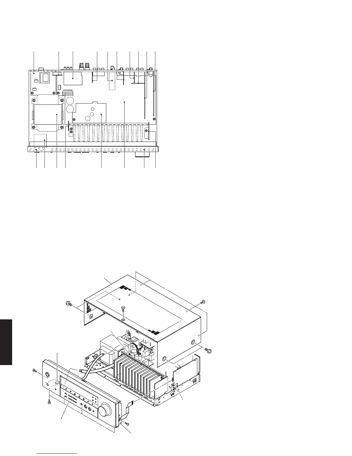
1 MAIN (2) P.C.B.
2 MAIN (6) P.C.B. (U, C models)
FUNCTION (7) P.C.B. (R, L models)
3 MAIN (4) P.C.B.
4 MAIN (5) P.C.B.
5 Tuner
6 MAIN (3) P.C.B.
7 FUNCTION (3) P.C.B.
8 FUNCTION (6) P.C.B.
9 FUNCTION (1) P.C.B.
0 DSP P.C.B.
A FUNCTION (9) P.C.B.
B FUNCTION (2) P.C.B.
C MAIN (1) P.C.B.
D FUNCTION (4) P.C.B.
E FUNCTION (8) P.C.B.
F Power Transformer
G FUNCTION (10) P.C.B.
H FUNCTION (5) P.C.B.
54 6 7
9 0
E
■ INTERNAL VIEW
2
2
1
1
3
3
3
Top Cover
CB653
CB804
Hook
Front Panel Unit
CB431
 Loading...